— 3 —
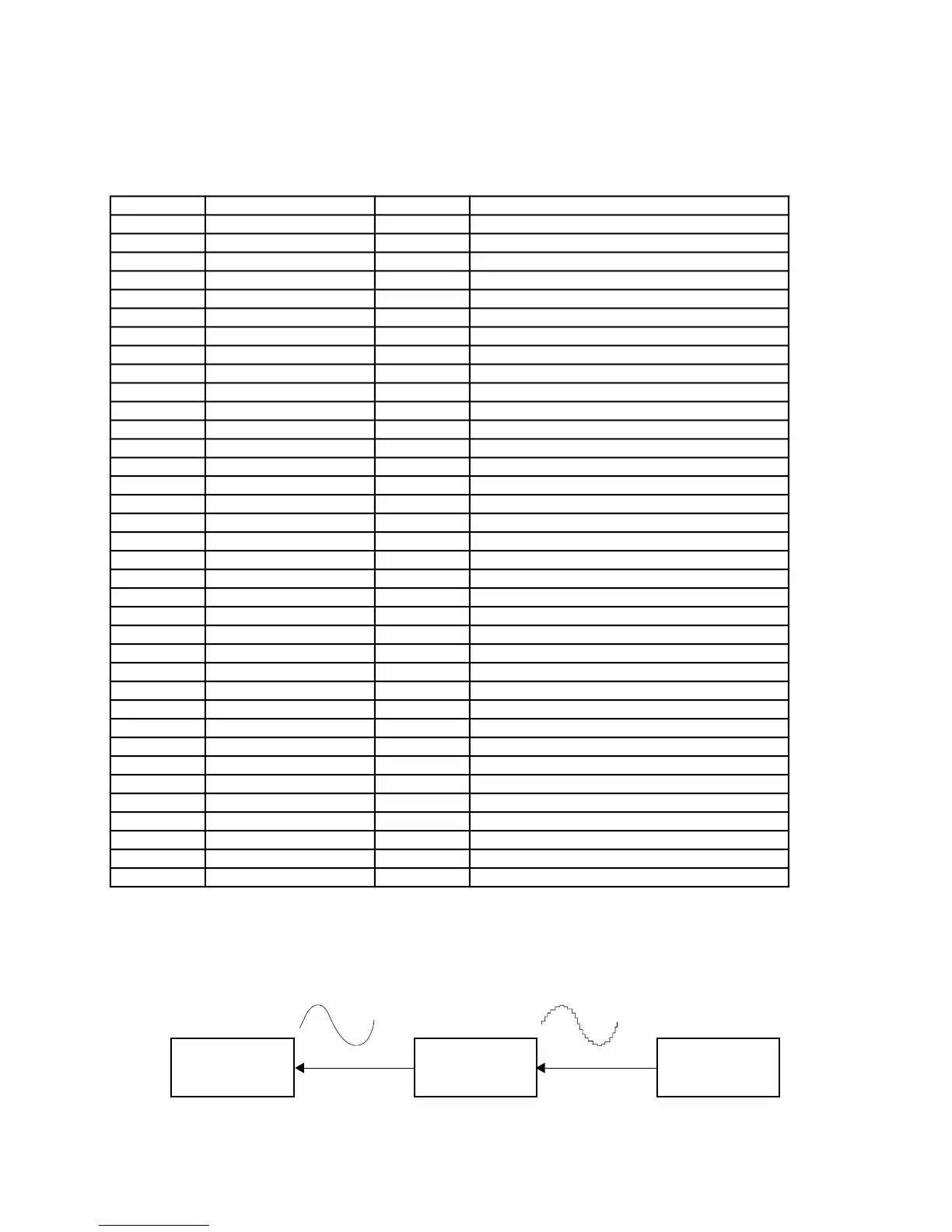
Amp.
LA4598
Filter
Block
CPU
MSM6755B-08
Pin No. Terminal In/Out Function
1 ~ 29 MA14 ~ NC2 — Not used.
30 DGND In Ground (0 V) source
31 DVCC In +5 V source
32, 33 XTLO, XTLI In/Out 20 MHz clock input/output
34 NC3 — Not used. Connected to ground.
35 RSTB In Reset signal input
36 P24/RXD — Not used. Connected to +5 V.
37 P25/TXD — Not used.
38 NMI In Power on signal input. Connected to +5 V.
39 APO Out APO (Auto Power Off) signal output
40 NC4 — Not used.
41 REFH Out Terminal for the built-in DAC
42, 43 NC5, NC6 — Not used.
44 DAOR Out Right channel sound waveform output
45 NC7 — Not used.
46 AVdac In +5 V source for the built-in DAC and ADC
47 DAOL Out Left channel sound waveform output
48 REFL Out Terminal for the built-in DAC and ADC
49 AGdac In Ground source for the built-in DAC
50 AGadc In Ground source for the built-in ADC
51 ANI — Not used. Connected to ground.
52 AVadc In +5 V source for the internal ADC
53 NC8 — Not used. Connected to +5 V.
54 MOD0 In Mode selection terminal
55, 56 MOD1, MOD2 In Mode selection terminal
57 KO9/P40 In APO cancelation signal input
58 ~ 65 KI0/P30 ~ KI7/P37 In Terminals for key/button input signal
66 ~ 73 KO1/P50 ~ KO8/P57 Out Terminals for key scan signal
74 ~ 77 P20 ~ P23 Out Terminals for button scan signal
78 NC9 — Not used.
79 LVCC In +5 V source
80 ~ 82 CC1 ~ CC3 Out LED common signal output
83 ~ 87 — — Not used.
88 ~ 95 La ~ Lg, Lp Out LED segment signal output
96 LGND In Ground (0 V) source
97 ~ 100 — — Not used.
CPU (LSI101: MSM6755B-06)
The CPU contains a sound data ROM and a DAC (Digital to Analog Convertor), and it provides left and right
channel sound waveforms in accordance with the pressed key and the selected tone.
The following table shows the pin functions of LSI101.
FILTER BLOCK
Since the sound signal from the CPU is a stepped waveform, the filter block is added to smooth the waveform.