— 11 —
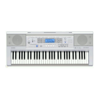
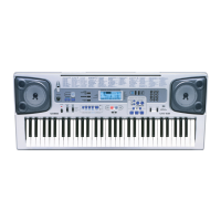
9. Remove 28 screws and then the PCB ASSY (CN1M).
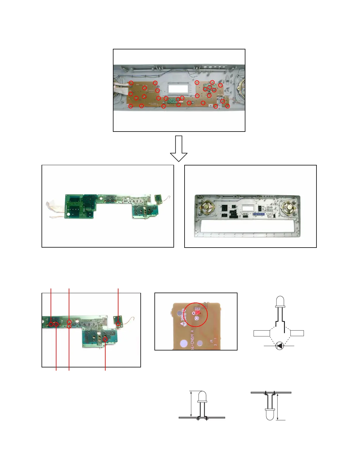
Note: Fix the LED (D4, D5, D50, D53, D54) to the PCB according to the height as shown in the figure below while
paying attention to the polarity.
Refer to the illustration on the PCB for the details of the polarity.
Anode
Cathode
8.7 ± 0.5 mm
D4,D54: 11.0 ± 0.5 mm
D5: 11.5 ± 0.5 mm
D53
D5 D54
D52
D4
D50
■ D50, D52, D53 ■ D4, D54
■ D5
 Loading...