— 11 —
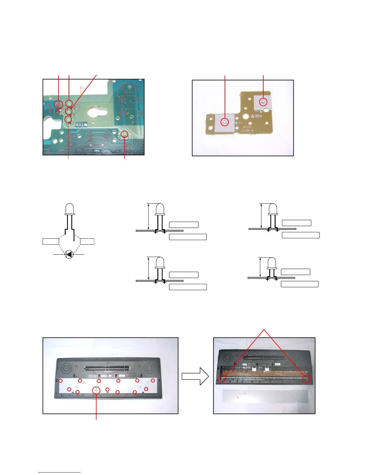
Note: Fix the LED (D301, D302, D303, D304, D305, D306, D307) to the PCB according to the height as shown in
the figure below while paying attention to the polarity.
Refer to the illustration on the PCB for the details of the polarity.
Anode
Cathode
D301
D302
D306
D303
D305
■ D301, D302
D307
9. Remove 13 screws and then the lower case.
Note: Tighten the screw with the arrow mark in the figure first when reassembling.
Cushion
D304
Note: Mount LED on the PCB. (solder side)
Correct polarity and height as follows.
■ D303, D304
15.0 ± 0.5 mm
SOLDER SIDE
COMPONENT SIDE
14.5 ± 0.5 mm
SOLDER SIDE
COMPONENT SIDE
■ D305 ■ D306, D307
12.5 ± 0.5 mm
SOLDER SIDE
COMPONENT SIDE
6.8 ± 0.5 mm
SOLDER SIDE
COMPONENT SIDE
 Loading...