– 61 –
DT-X200/DT-X8
6-3-3. All MODEL
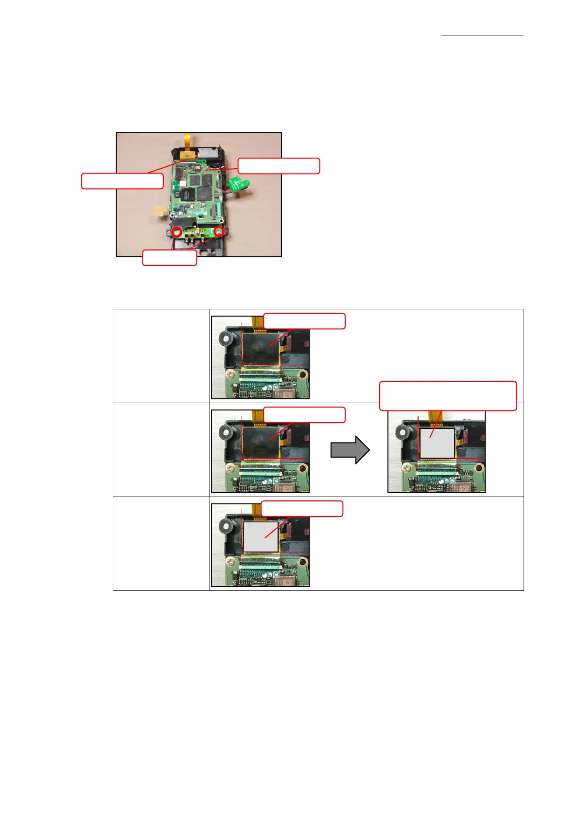
(1) Removing the MAIN-PCB
1. Remove the screws S7 (2 pcs.).
2. Peel off the tape, unlock the connector lock, and remove the FPC.
3. Disconnect the Antenna Cable.
Screws S7
FPC
Antenna Cable
Note on reassembling:
• Attach the BLIND tape and the EMI-SHEET.
DT-X200-20E
DT-X200-20C-CNV
(BLIND tape only)
BLIND tape
DT-X200-21E
(BLIND tape and
EMI-SHEET)
BLIND tape
DT-X200-41E
(EMI-SHEET only)
EMI-SHEET
EMI-SHEET
Attach it over the BLIND tape.
 Loading...