Do you have a question about the Casio PX-780 and is the answer not in the manual?
Safety and handling guidelines for charging, feeding, batteries, printer, paper, and general use.
Recommendations for storing the product to prevent damage and maintain condition.
General safety warnings related to battery replacement and disposal.
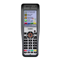
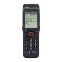
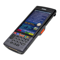
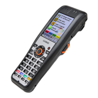
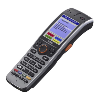
Overview of the IT-3100 series as an enhanced handheld terminal from the IT-3000 series.
Table detailing hardware configurations across different IT-3100 models.
List of optional accessories available for the IT-3100 series.
Details CPU, OS, Memory, Display, Imager, IR, Serial, and Bluetooth specifications.
Specifics on printer capabilities, power requirements, operating environment, and physical characteristics.
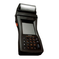
Identification and description of various physical parts of the IT-3100 terminal.
Explanation of the purpose and operation of each key on the terminal.
Schematic showing the electrical connections between major components of the terminal.
Diagram illustrating the overall system architecture and component interconnections.
Layout and connector identification for the Main Printed Circuit Board.
Visual representation of component placement on the main PCB.
Troubleshooting flowchart for power-on issues, including checks for battery, connectors, and PCBs.
Diagnostic procedures for failures related to keys, touch panel, and LCD.
Troubleshooting steps for problems with the scanner LED and various sensors.
Diagnostic flowcharts for issues with speaker, PCMCIA/SD cards, and charge LED.
Troubleshooting steps for communication interface problems including IrDA, 8-pin, and Bluetooth.
Diagnostic procedures for printer, key backlight, and magnetic card reader faults.
Troubleshooting flowchart for issues with the CMOS imager, including connection and FPC checks.
Explains factors that turn the device ON, prevent it from turning ON, and turn it OFF.
Details power saving features like Idle state, CPU frequency, Auto Power Off, Dimmer, and Backlight Off.
How temperature affects backlight brightness and its automatic restriction.
Details the four low voltage detection levels and battery status monitoring.
Step-by-step instructions for attaching and removing the neck strap.
Procedure to calibrate the touch screen response for accurate input.
Steps to adjust display contrast and screen brightness for better readability.
How to adjust screen brightness and configure the auto-dimmer feature.
Instructions for using the C-MOS Imager to read bar codes and 2D codes.
Safety warnings regarding laser light exposure from the C-MOS Imager.
Instructions for reading magnetic cards and precautions during use.
Procedures for IR and RS-232C data communication.
Instructions for Bluetooth data transfer and precautions for interference.
Steps to perform a standard reset and its effects on the terminal.
Detailed procedure for performing a full reset (initialization) of the device.
How to obtain and use the service utility software for hardware testing.
Instructions for booting and navigating the diagnostic program.
Table of inspection items, target models, tools, and guide pages for functional testing.
Detailed steps for testing the SDRAM functionality using the diagnostic program.
Detailed steps for testing the NAND-FROM functionality using the diagnostic program.
Detailed steps for testing the functionality of all keys and buttons.
Detailed steps for testing the touch panel functionality.
Steps for testing LCD patterns, VCOM, and LED backlight adjustment.
Steps to test the scanner LED colors (red, green, orange).
Testing of Battery Voltage, LCD/CPU Temperature, and Bright Sensor.
Testing of speaker audio output and volume levels.
Steps for checking the PCMCIA card slot and functionality.
Steps for checking the SD card slot and functionality.
Testing of the Magnetic Card Reader (MCR) functionality with diagnostic cards.
Testing the key backlight functionality (ON/OFF).
Steps to test printer functionality, specifications, and printing output.
Procedure to test the paper sensor and marker detection.
Steps to test the charge LED indicator status during charging.
Initial setup for testing IrDA communication, including driver installation and PC connection.
Steps for initiating Bluetooth tests using diagnostic software on the device and opponent.
Steps to test the CMOS Imager functionality by scanning symbols.
Table of items and tools for measuring operational, idle, and print current consumption.
Detailed procedure for measuring operational current using the diagnostic program.
Procedures for measuring idle current and print current consumption.
Table showing required jobs for PCB or LCD module replacement.
Lists the specialized tools required for LCD intensity and flicker adjustments.
Steps to adjust LCD brightness to a specific level using a display tester.
Steps to adjust LCD flicker to a minimum level using a display tester.
Procedure for registering the device's serial number and scanner type.
How to confirm the registered serial number and scanner type.
Procedure to set the model status before function tests.
Step-by-step guide for disassembling the Roll Paper Holder and separating the case.
Instructions for removing screws, opening the case, and handling FPC cables.
Procedures for removing the middle case and the main PCB.
Steps for removing the printer unit from the device.
Procedures for removing the LCD shield, touch panel, and LCD module.
Guidelines for processing FPC cables during assembly.
Step-by-step guide for assembling the Magnetic Card Reader unit.
Step-by-step guide for assembling the CMOS Imager module.
Instructions for correctly applying plastic sheets to the battery pack.
Procedures for removing and attaching the Paper Sensor PCB.
Instructions for applying shield sheets to FFC/FPC cables for protection.
Step-by-step guide for assembling the Power Key PCB.
Important information regarding changes in MAIN PCB ASSY versions and replacement procedures.
Exploded view of the complete handheld terminal assembly.
Detailed exploded view of the upper case components and FPC connections.
Detailed exploded view of inner case components and connector FPCs.
Detailed exploded views of lower case and MCR block components.
Exploded view of the roll paper holder components.
Images and descriptions of labels applied to the terminal.
List and images of accessories included in the package.
List of part numbers and names for the Upper Case Assembly.
List of part numbers and names for the Inner Case Assembly.
Parts list for Lower Case and Roll Paper Holder assemblies.
Parts list for other components like MCR, CMOS Imager, and insulation sheets.
Parts list for tools and special screws used for the device.
Recommended paper types and specifications for 1-ply paper.
Recommended 2-ply formed and label paper types and specifications.
Sample test sheet for calibrating the paper marker sensor.
Sample test sheet for calibrating paper marker detection.
| Touch Response | 3 sensitivity levels, Off |
|---|---|
| Speakers | 12cm x 2, 5cm x 2 |
| Sound Source | Multi-dimensional Morphing AiR |
| Maximum Polyphony | 128 |
| Number of Tones | 18 |
| Digital Effects | Reverb (4 types), Chorus (4 types), Brilliance, DSP (some tones) |
| Recorder | [MIDI Recorder] 2 tracks, 1 song, Approximately 5, 000 notes total |
| Pedals | 3 (Damper, Soft, Sostenuto) |
| Keyboard | 88-key, Scaled Hammer Action Keyboard |