— 7 —
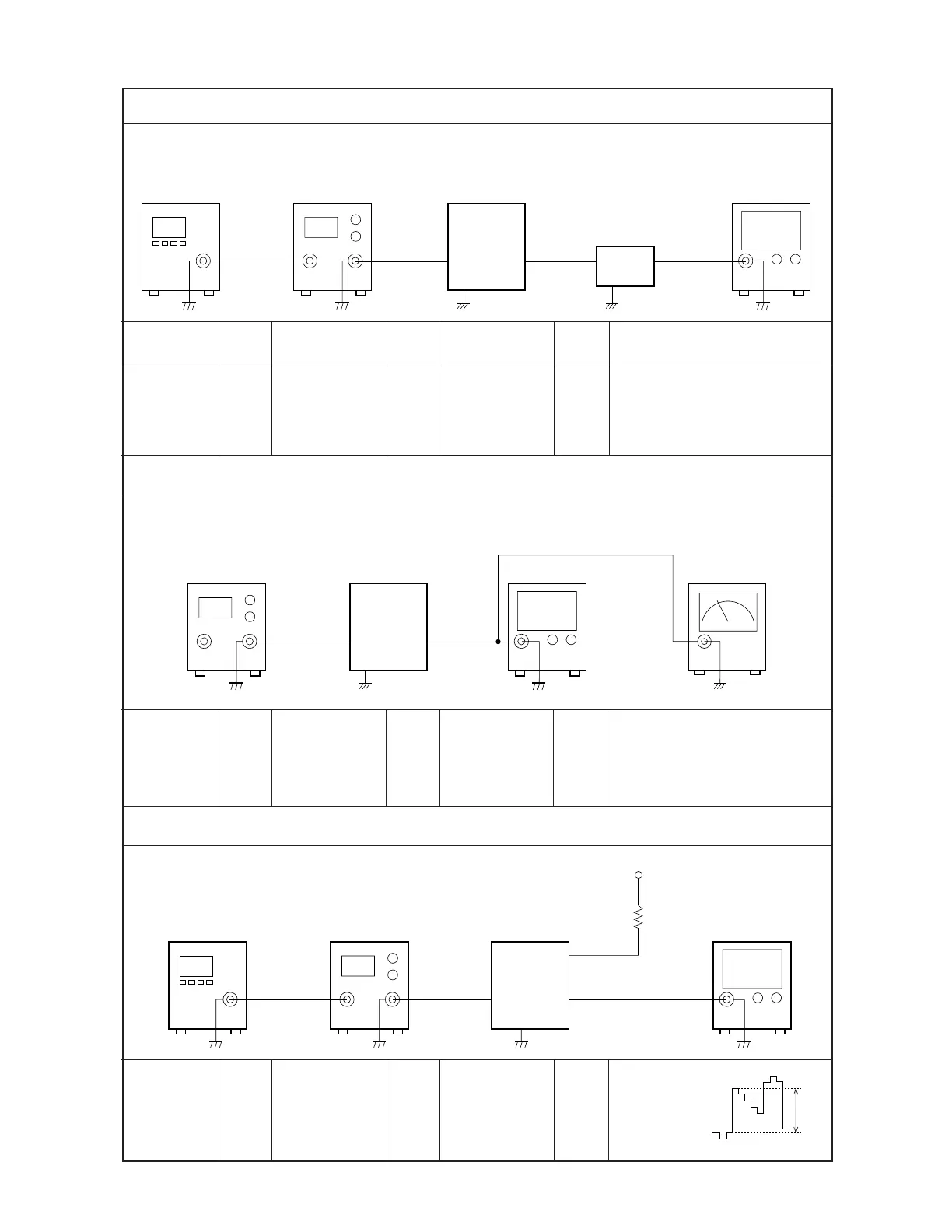
Video Detection Coil Adjustment
TP2 VR300 TP5
Pattern
generator
Signal
generator
Oscilloscope
* Desolder the IF pad to open.
Contrast Adjustment
TP2 T201 TP4
Adjust to obtain a 1.4 ± 0.2 V
reading on the voltmeter.
Confirm that the marker is at
the middle of the S-curve on
the oscilloscope.
* Desolder the IF pad to open.
AFT Coil Adjustment
Pattern
generator
Signal
generator
TP2 T200 TP3
Input Input Input Output Output
Connection Point Signal Connection Point
Adjust Result
* Desolder the IF pad to open.
Voltmeter
Oscilloscope
Sweep
generator
Pattern
generator
Signal
generator
Input
TP2
CP312 (KILLER)
Oscilloscope
Vcc2-3
EV-500
set
10 kohm
Adjust so
that the step
form wave
becomes 2.2
± 0.1 Vp-p.
Adjust to obtain the minimum
DC level.
Low-pass filter
Oscilloscope
2.2±0.1 V
P.P
Input
TP2
EV-500
set
Output
TP3
Low-pass
filter
Pattern
generator
Signal
generator
Oscilloscope
Sweep
generator
EV-500
set
Input
TP2
Output
TP4
Voltmeter
Oscilloscope
Color bar
38.9 MHz
(EV-200C,I,N)
39.5 MHz
(EV-200D)
45 ± 3 dBµ
38.9 ± 5 MHz
(sweep) marker:
38.9 MHz (EV-200C,I,N)
39.5 ± 5 MHz
(sweep) marker:
39.5 MHz (EV-200D)
70 ± 3 dBµ
Output
TP5(VC)
Color bar
38.9 MHz
(EV-200C,I,N)
39.5 MHz
(EV-200D)
70 ± 3 dBµ