— 8 —
* Desolder the IF pad to open.
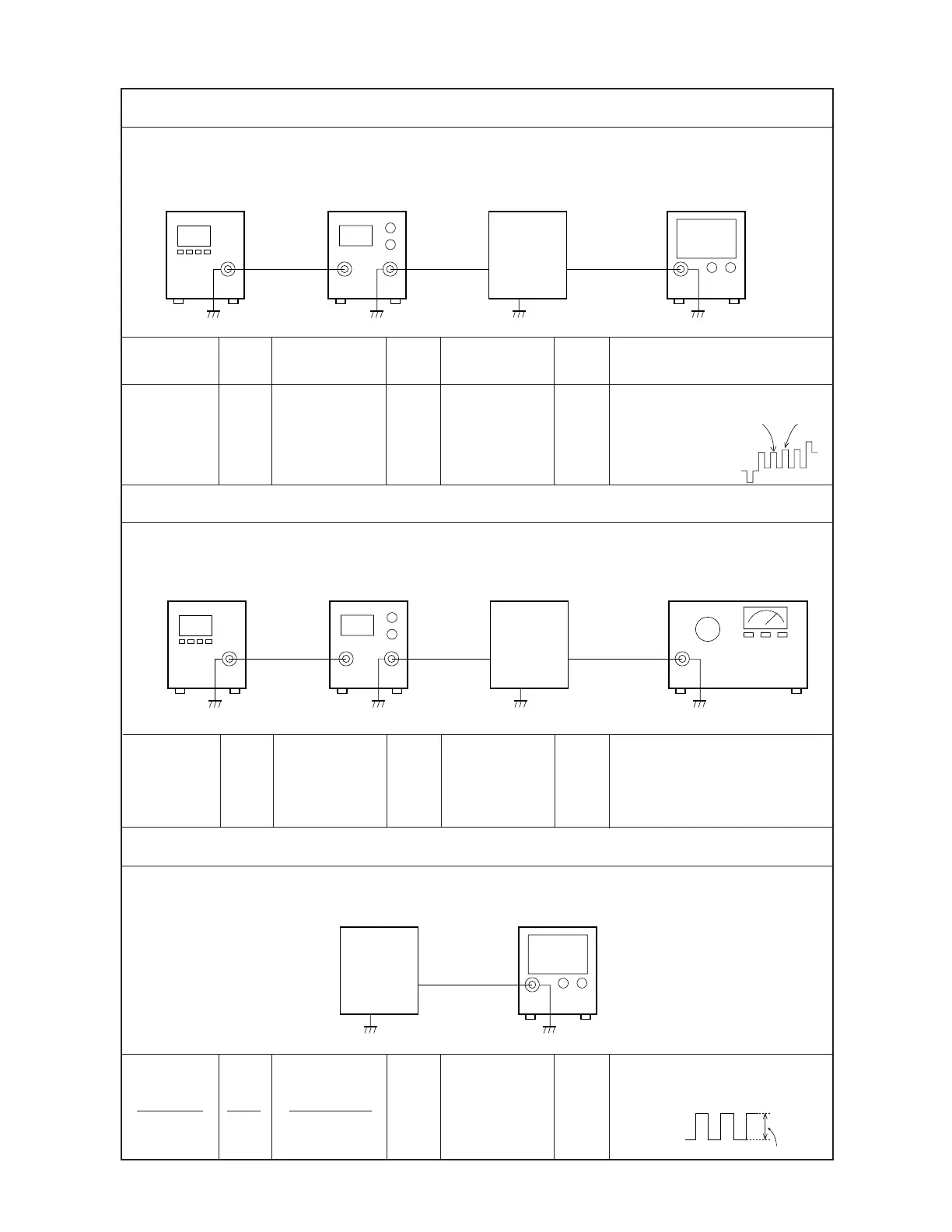
BCC Adjustment
Signal
generator
Pattern
generator
EV-500
set
Oscilloscope
Input
TP2
Output
TP5(VC)
Input Input Input Output Output
Connection Point Signal Connection Point
Adjust Result
Pattern
generator
Signal
generator
TP2 T300 Oscilloscope TP5
Adjust T300 so that the
difference
between pulses
A and B is less
than 0.2 V.
Pulse BPulse A
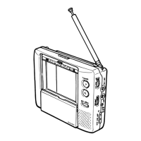
AGC Adjustment
Signal
generator
Pattern
generator
EV-500
set
IF levelmeter
Input
TP7
Output
TP2
* Short the IF pad.
Pattern
generator
TV signal
generator
TP7 VR200 IF levelmeter TP2
Color bar
65 ± 5 dBµ
Adjust to obtain a 84 ± 2 dBµ
reading on the IF levelmeter.
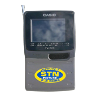
Vcom Adjustment
EV-500
set
Oscilloscope
Output
TP8
Color bar
38.9 MHz
(EV-200C,I,N)
39.5 MHz
(EV-200D)
70 ± 3 dBµ
5.0 ± 0.5 V
-0.5 ± 0.25 V
VR303 Oscilloscope TP8
Adjust VR303 so that the
high level of the square wave
is at -0.3
± 0.25 V.