— 17 —
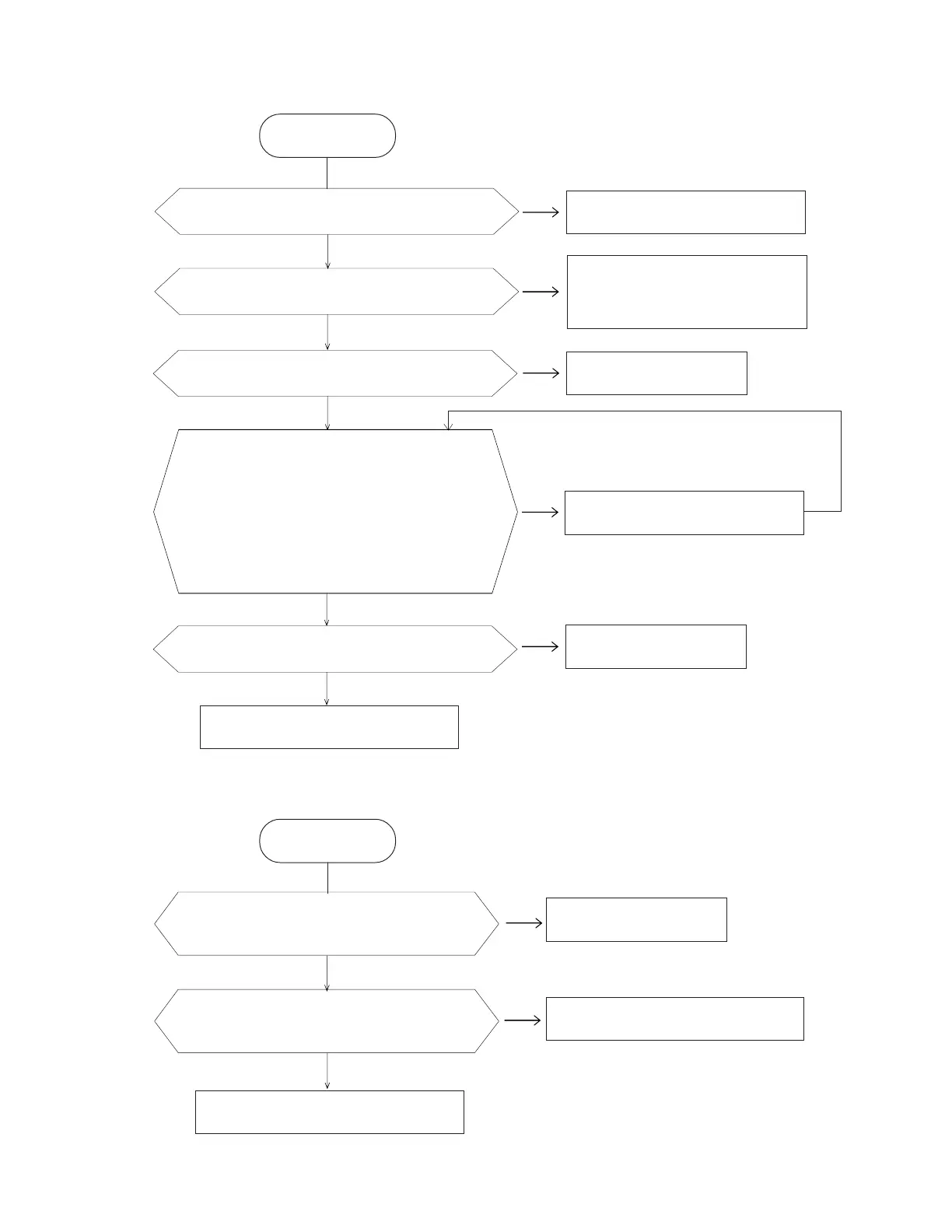
No/Erratic display
N
Y
Is input Pin 2 of REG1 6 V?
N
Adjust the contact and clean
the battery springs.
Y
Is output Pin 3 of REG1 5.3 V?
N
Y
N
Y
Are the voltages of V1, V2, V3, and V4
strong enough?
V1: 1.3 V
V2: 2.5 V
V3: 2.7 V
V4: 3.9 V
Is the soldering of LSI1 poor?
N
Replace LSI1.
Y
Resolder.
High current consumption
START
Y
N
Are the capacitors C8, C9, C11, C12,
and C13 OK?
N
Y
Is there any short circuit on the PCB
assembly ?
START
Note:
Contrast: Maximum
Replace C1, C2, C3, or C4.
Repair shorts.
Resolder or replace LSIs and ICs.
Replace the capacitor(s).
Replace REG1.
Replace the batteries.
Are the power of batteries strong enough?
 Loading...