— 6 —
Oscillator
20 MHz
CPU
APO
DVDD
DVDD
From power switch
SWITCH: OFF ON
+5 V +5 V 0 V
APO: "L" "H"
+7.5 V 0 V
AMPLIFIER/VOLTAGE REGULATOR (IC101: AN8053N)
The right figure shows the internal block of IC 101.
16 9
SP AMP
–
+
VREF
5V REG
POWER
1 34567 82
15 14 13 12 11 10
VCC NC CONT
5 V
VREG NC NC NC PRE GND
SPO NC SP GND PC-1 PC-2 SPI SPM VREF
POWER SUPPLY CIRCUIT
The power supply circuit generates two voltages DVDD (+5 V) and AVDD (+5 V). DVDD (+5 V) is always
generated but AVDD (+5 V) is controlled by APO signal output from the CPU.
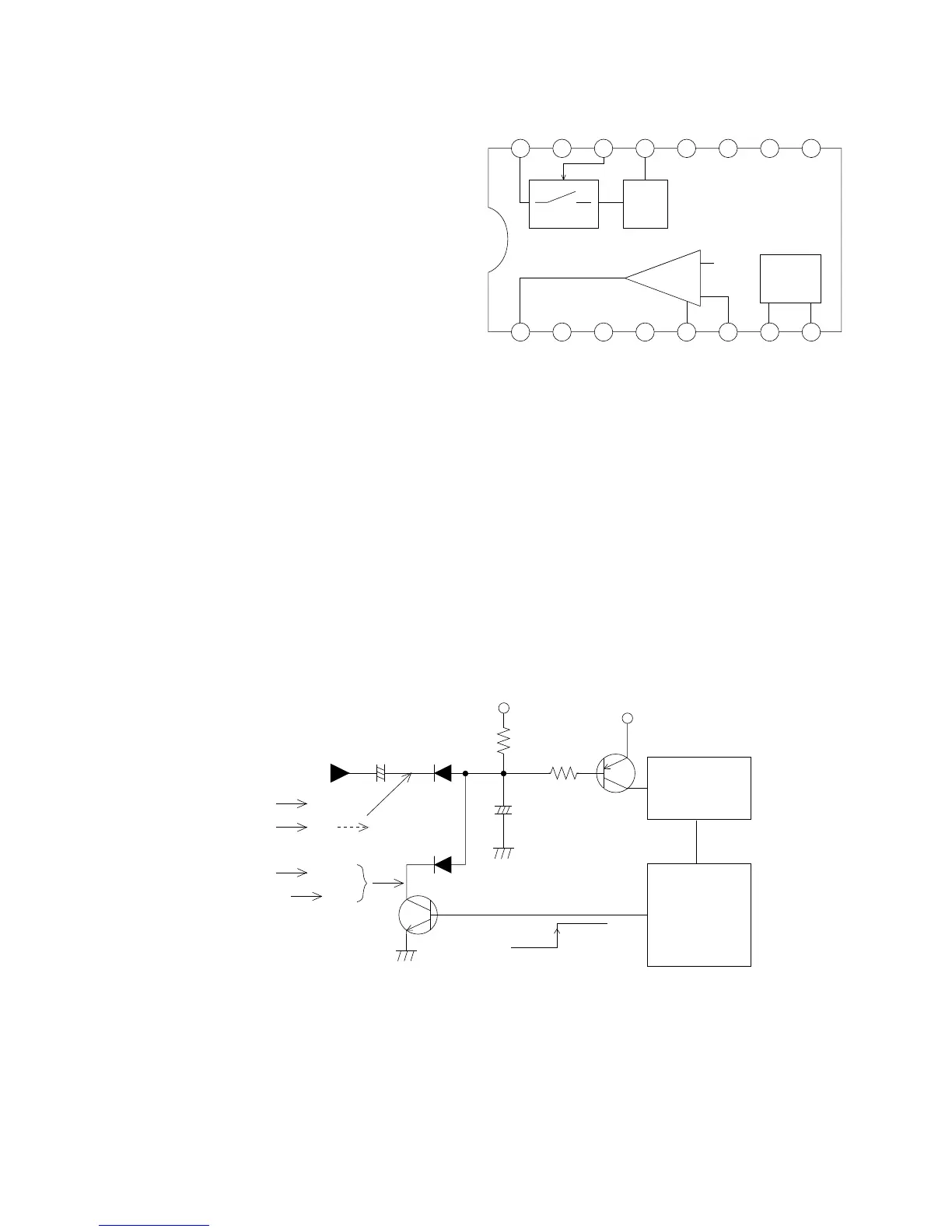
OSCILLATOR
+5 V source of the oscillator is controlled by transistor Q107. When selecting the power switch at on position,
transistor Q107 turns on to become 20 MHz oscillation on. To keep the oscillation on, the CPU provides "H"
of APO signal.
 Loading...