-3-
N.B. If th i s ad jus tme nt is n ot cor re ct wedge in se rt i on c a nn o t t a k e pla ce
For safety reasons when no moulding is in place wedge insertion
cannot occur.
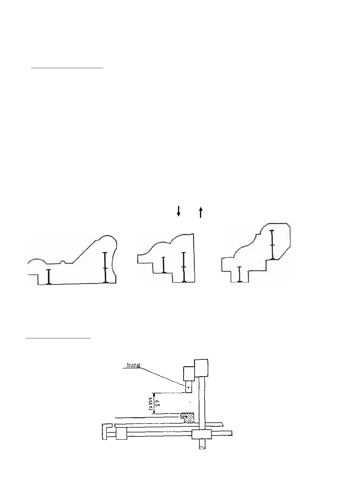
POSITIONING THE WEDGES (see Fig. 3)
Either t ur n off the air or switch off at the main switch.
Loosen th e handles X a nd W.
Slide th e cross bar (E) until th e distributor he ad (H) is in t h e co rr ec t position
f or the r ear wedge.
Slide th e loc kin g handle fo rwa rd (W) and lock in to position.
Slide th e cross bar to th e fo rwa rd position a nd slide the handle (X) to the
rear an d tighten.
If wedges are being inserted at different levels check by raising the head with
the lever HA that no part of the moulding will prevent th e distributor head
rising to the correct position.
In order to select the number of wedges press t he keys 1 a n d 2.
Key 1 always corresponds to th e position where th e first wedge will be inserted.
This position is selected by the arrow keys and
Fig 3
SETTING THE BUNG (0)
Check th at t h e height between the top of the moulding and t he bottom of the bung
islessthan45mm(13/4").(seeFig.4)
Fig 4
moulding