Do you have a question about the Cassese MACH 1 UNI and is the answer not in the manual?
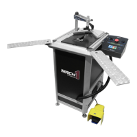
Identifies key working positions on the machine for setup and operation.
Details the manufacturer and their experience in framing machines.
Lists the standard accessories provided with the MACH 1 UNI.
Outlines the machine's dimensions, weight, and performance limits.
Describes optional equipment available for the machine.
Details the warranty terms for the MACH 1 UNI.
Step-by-step guide for unpacking the MACH 1 UNI from its packaging.
Details the air line fittings required for the machine.
Instructions for connecting the machine to the compressed air supply.
Procedure for powering on and initializing the machine for first use.
Proper adjustment of the magnetic adjustable rod clamp assembly.
Guidance on using spacer bars for small mouldings.
How to select the desired stapling positions on the machine.
Steps for adjusting the frame joining angle for accuracy.
Explains the joining process using metal wedges.
Procedure for loading wedges into the machine.
Procedure for changing the stapling head to accommodate different wedge sizes.
Explanation of the information displayed on the machine's screen.
How to select between Manual and Automatic stapling modes.
Setting up stapling positions and specifying wedge quantities per position.
Managing saved stapling programs from F1 to F9.
Details the sequence and behavior of the stapling cycle.
Instructions for reloading wedges.
Understanding safety clamp alerts and operation.
How to access and navigate the machine's parameter menu.
Detailed explanations of specific machine parameters and their functions.
Critical safety precautions to follow before performing maintenance.
Procedure for removing and cleaning the stapling head.
Steps to remove the side panel for access to internal parts.
How to lubricate or replace the wedge driver for optimal performance.
Procedure for lubricating the machine's crossbar.
Troubleshooting steps for removing a jammed wedge.
Guide for replacing the elastic cord in the wedge distribution channel.
Comprehensive list of all spare parts with references and descriptions.
Overall exploded diagram of the MACH 1 UNI machine.
Detailed exploded view of the top clamp column assembly.
Detailed exploded view of the sliding table mechanism.
Detailed exploded view of the main mechanical components.
Detailed exploded view of the "UNI" rebate clamp.
Detailed exploded view of the "UNI" distribution channel.
Detailed exploded view of the rebate clamp bar.
Detailed exploded view of the wedge driver support assembly.
Detailed exploded view of the stapling position engine.
Detailed exploded view of the keyboard and control panel.
Detailed exploded view of the components drawer.
Detailed exploded view of the extension arms.
| Brand | Cassese |
|---|---|
| Model | MACH 1 UNI |
| Category | Industrial Equipment |
| Language | English |