Do you have a question about the Castell KSS and is the answer not in the manual?
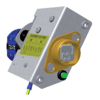
Describes the key release sequence involving solenoid energization and LED indication.
Explains its role in safety systems for hazardous area access, not for security.
Details panel mounting, sealing, and cable connection according to wiring diagrams.
Mandates anti-tamper fasteners and installation by qualified personnel.
Outlines periodic checks, lubrication guidelines, and defect reporting procedures.
Lists technical parameters including temperature, weight, material, and power ratings.
Describes its use in machine guarding, often with access interlocks for safe entry.
Details the sequence for machine shutdown, key release, and access enablement.
Manufacturer declares compliance with essential health and safety requirements.
Shows detailed dimensions for the panel mount (Back of Board) configuration.
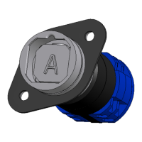
Shows detailed dimensions for the surface mount (Front of Board) enclosure.
Provides precise panel cut-out dimensions and hole sizes for supply connections.
Illustrates the specific wiring connections for AC powered KSS units.
Illustrates the specific wiring connections for DC powered KSS units.
Explains how to select options to create a specific product part number.
Lists various options for isolation, lock type, material, and contacts.
Lists available accessories like the Flip Cap for the KSS switch.
Provides contact information for UK and European offices for assistance.
| Model | KSS |
|---|---|
| Material | Metal |
| Actuation Force | Varies by model, consult specific datasheet |
| Travel Distance | Varies by model, consult specific datasheet |
| Lifespan | Varies by model, consult specific datasheet |
| Operating Temperature | -20°C to +80°C (typical range, may vary) |
| Contact Resistance | Varies by model, consult specific datasheet |
| Insulation Resistance | Varies by model, consult specific datasheet |
| Dielectric Strength | Varies by model, consult specific datasheet |