OPERATION
4
LS-1700/LS-1700HD/TS-1700HD/LS-2000/LS-2000HD/TS-2000HD (01–00)
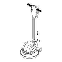
MACHINE COMPONENTS
1
4
5
10
13
8
9
2
3
12
6
7
11
1. Handle Grips
2. Control Triggers
3. Safety Lock Button
4. Dual Speed Switch (Dual Speed Model)
5. Circuit Breaker Reset Button
6. Quick Release Power Cord Hook
7. 15 m (50 ft) Power Cord
8. Cord Grip
9. Handle Release Foot Lever
10. Motor Cover
11. Wheels 100 mm (4 in)
12. Handle Lock Knob
13. Brush/Pad Driver
MACHINE SETUP
1. Carefully check carton for signs of damage.
Report damages at once to carrier.
2. Unfold handle to the upright position and lock
handle using the handle lock knob (Figure 1).
FIG. 1
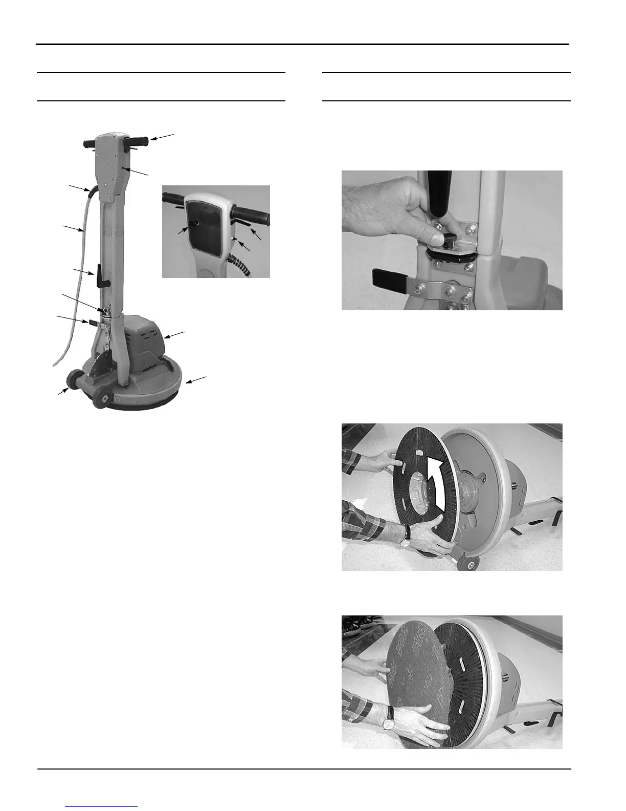
3. Carefully tilt machine back on handle and install
brush/pad driver.
NOTE: Pad driver, pads and brush are sold
separately. Consult your authorized distributor for
pad/brush recommendations.
4. Position brush/pad driver on driver lug and turn
counterclockwise to secure (Figure 2).
FIG. 2
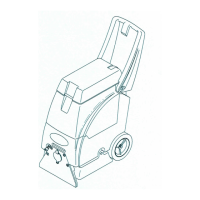
5. For pad installation, center pad on pad driver and
tap with hand to secure (Figure 3).
FIG. 3