SERVICING THE SEALS
Disassembly
1. Remove the Discharge Manifold as described in SERVICING
THE VALVES section.
2. To service the seals the Inlet Manifold must be removed,
use a M10 allen wrench to remove the 4 Socket Head
Screws.
3. Support the Inlet Manifold and lightly tap the top back side
with a soft mallet. Remove the Inlet Manifold and place it
crankcase side down.
4. Use a reverse pliers to remove the Hi-Pressure Seals.
5. The Lo-Pressure Seals may stay on the Plungers or in the
Inlet Manifold.
6. Invert the Inlet Manifold with the crankcase side up.
7. Remove the Lo-Pressure Seal using a reverse pliers or
slide it off the Plunger by hand.
Reassembly
NOTE: If your pump has been built with special seals
and O-Rings, service with same type of special parts.
Refer to pump Data Sheet for correct parts or kits.
NOTE: For certain applications apply liquid gasket to
the O-Ring crevices and seal surfaces. See Tech
Bulletin 053 for model identification.
NOTE: EPDM elastomers require a silicone-base
lubricant.
1. Examine the Lo-Pressure Seal for wear or spring fatigue
and replace. Apply liquid gasket to the outside of the new
Lo-Pressure Seal and carefully press it into the Inlet
Manifold chamber with the spring down.
NOTE: When using alternate materials, the fit of the
special materials may be snug and require gently
driving the LPS into position with a cylinder of the
same diameter to assure a square seating and no
damage to the LPS.
2. Invert the Inlet Manifold and place the crankcase side
down. Examine the Hi-Pressure Seal for deformity or
wear and replace. Apply liquid gasket to the outside of the
new Hi-Pressure Seal and carefully press it into the Inlet
Manifold chamber with the metal side down.
SERVICING THE PLUNGERS
Disassembly
NOTE: The Ceramic Plungers and the Plunger
Retainers should be examined on the same schedule
as servicing the seals.
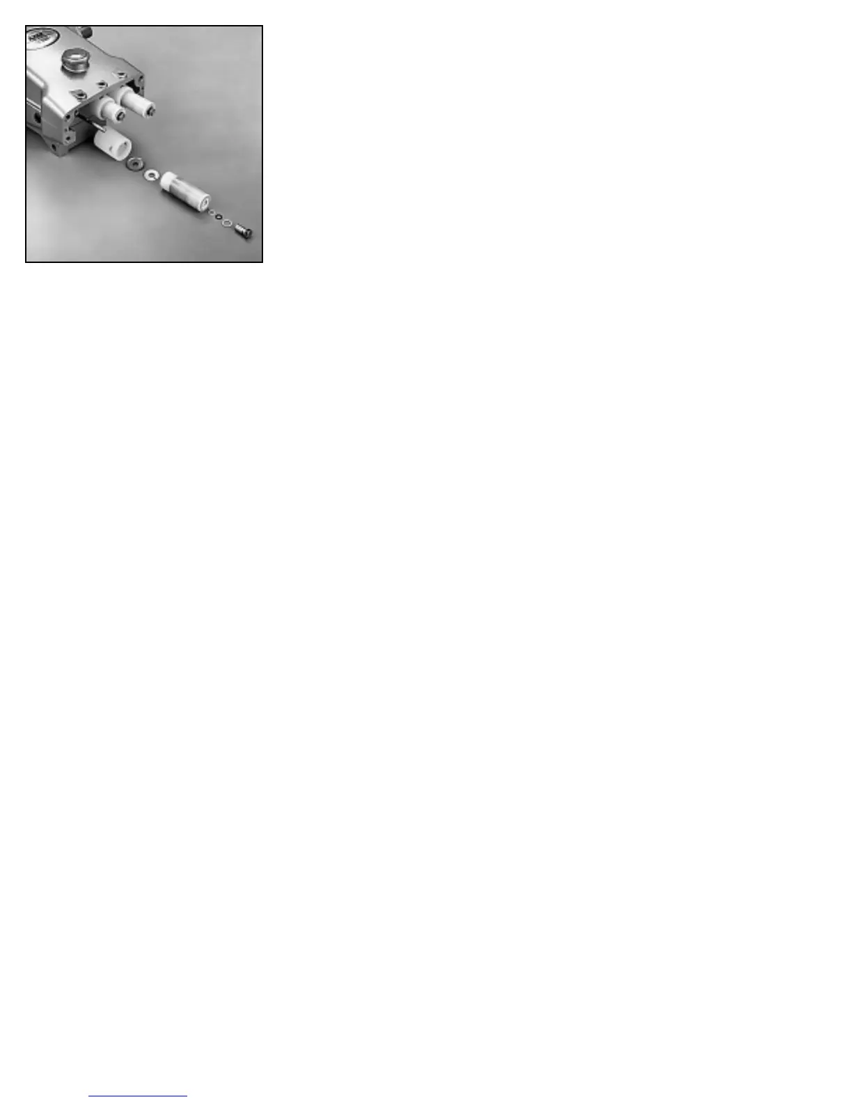
1. To service the Ceramic Plungers, first remove the Seal
Retainers.
2. Loosen the Plunger Retainer about three or four turns
using a M14 hex tool.
3. Grasp the Ceramic Plunger and push toward the
Crankcase until it separates from the Plunger Retainer.
4. Unthread the Plunger Retainer with Gasket, O-Ring,
Back-up-Ring and Ceramic Plunger. Remove the Keyhole
Washer and Barrier Slinger from the Plunger Rod.
Reassembly
1. Examine the Barrier Slinger for any wear or damage and
place on the Plunger Rod with the concave side facing
out.
2. Examine the Keyhole Washer and place on the Plunger
Rod with the slot down.
3. Examine the O-Ring and Back-up-Ring on the Plunger
Retainer and replace if worn or damaged. First install
the Gasket, then the O-Ring and Back-up-Ring. Lubricate
the Plunger Retainer O-Ring to avoid cutting during
installation.
4. If the Plunger Retainer unthreads from the stud during re-
moval, thread the stud into the retainer.
5. Examine the Ceramic Plunger for scoring, cracks or scale
and replace if needed. The Ceramic Plunger can be
cleaned with a scotchbrite pad. Slide the Ceramic Plunger
onto the retainer and stud assembly with the shallower
counterbore away from the retainer.
NOTE: Plunger can only be installed one direction. Do
not force into Plunger Rod.
NOTE: Do not lubricate wicks at initial start-up.
Operate for 10 to 15 minutes to allow grease from
LPS to penetrate the plunger surface, then lubricate
as needed.
6. Apply Loctite
®
242
®
to the threads of the Plunger Retainer
Stud and thread onto the Plunger Rod. Then torque to
specifications in chart.
Plunger Arrangement