i03734066
Product Description
SMCS Code: 1000; 4450; 4491; 7000
Intended Use
This Power Generator is intended to be used to
generate electrical power.
Engine Description
The 3412C Generator Set engine is a 12 cylinder
engine. The direct injection engine has a four stroke
cycle. Each cylinder head has two inlet valves and
two exhaust valves. The rocker arms and the valves
are actuated by the camshaft. Mechanical lifters and
pushrods perform the function.
A hydramechanical governor or an electronic control
controls the output of the fuel injection pump. The
operator maintains the engine rpm. The fuel injection
pump meters the fuel and the fuel injection pump
pumps the fuel. The high pressure gaseous fuel is
pumped to the fuel injection nozzles. The mechanical
timing advance provides the best fuel injection timing
over the full range of engine speeds.
Inlet air is filtered by the air cleaner. The air is
compressed by the turbocharger before the air enters
the cylinders. The turbocharger is driven by the
engine exhaust. The standard engine is
turbocharged, available with aftercooling or no
aftercooling.
The cooling system consists of the following
components:
• A gear-driven centrifugal pump
• One water temperature regulator which regulates
the engine coolant temperature
• An oil cooler
• A radiator which incorporates a shunt system
The engine lubricating oil is cooled and the engine
lubricating oil is filtered. The engine lubricating oil is
supplied by a gear-driven pump. If the oil viscosity is
high or if the oil cooler and oil filter elements become
plugged, bypass valves provide unrestricted flow of
lubrication oil to the engine.
Engine efficiency and engine performance depend
on adherence to proper operation and maintenance
recommendations. Use the recommended fuel,
lubrication oil, and coolant. Special attention should
be given to the air cleaner, to the fuel system, to the
lubrication system, and to the cooling system
maintenance. Refer to the Operation and
Maintenance Manual, “Maintenance Interval
Schedule” for more information on maintenance
items.
Engine Specifications
Note: The front end of the engine is opposite the
flywheel end of the engine. The left and the right side
of the engine are determined from the flywheel end.
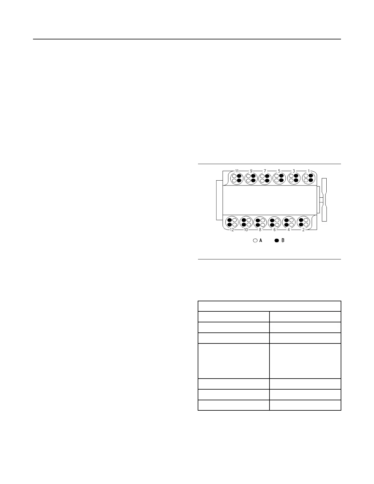
Illustration 22 g00291566
Cylinder and valve locations
(A) Inlet valves
(B) Exhaust valves
Table 1
3412C Engine Specifications
Cylinders and Arrangement 12 cylinder vee block
Bore 137 mm (5.4 inch)
Stroke 152.4 mm (6.00 inch)
Aspiration Turbocharged (T), Twin Turbo-
charged (TT), Twin Turbo-
charged Aftercooled (TTA),
Series Turbocharged After-
cooled (STA)
Displacement 27 L (1648 cu in)
Firing Order
1-4-9-8-5-2-11-10-3-6-7-12
Rotation (flywheel end)
Counterclockwise
(continued)
SEBU7125-13
19
Product Information Section
Product Description
 Loading...