SETUP AND PROGRAMMING CHAPTER 3
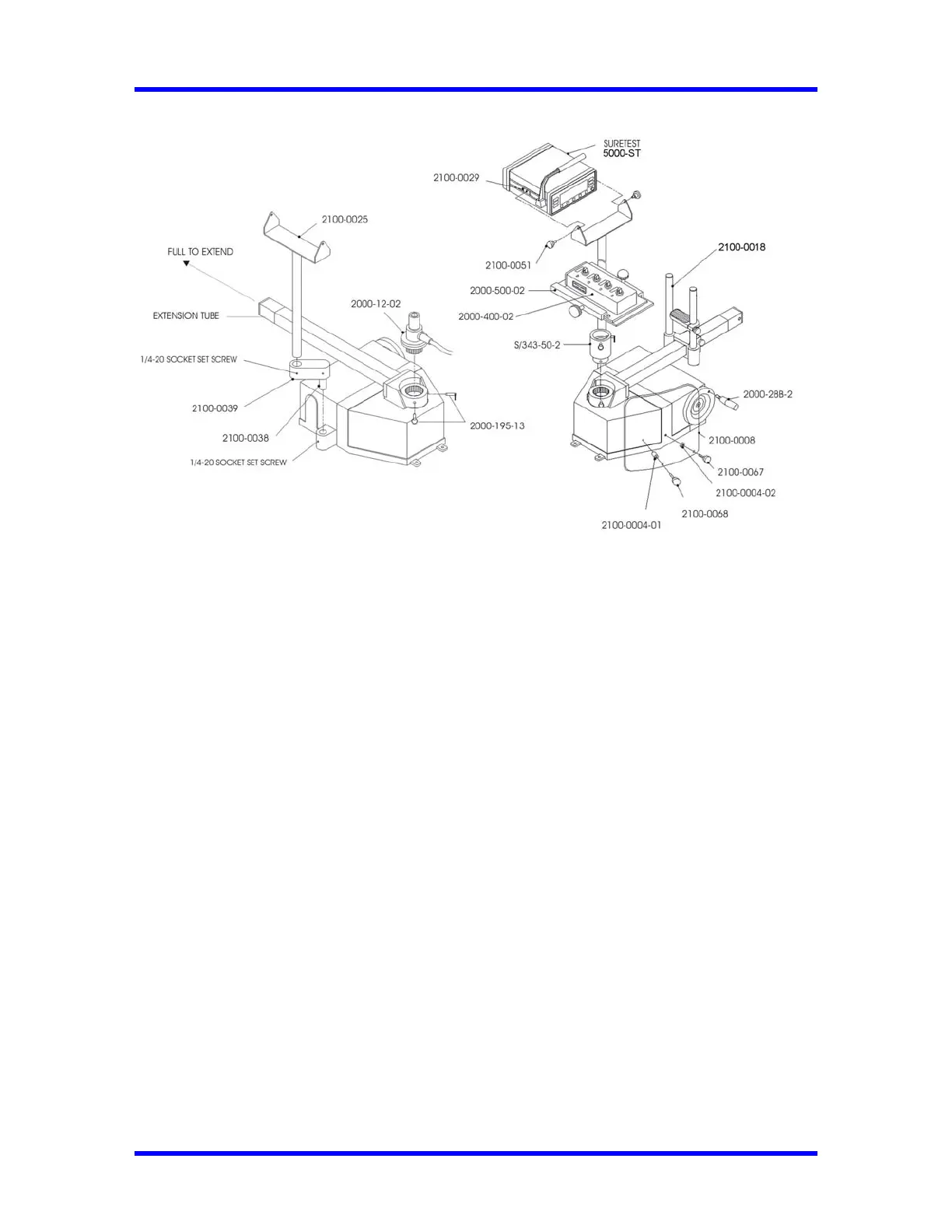
Setting Up the CDI 5000-3 Torque Calibration System
1. Bolt the loader to a sturdy location.
2. Install Pivot tube, Extension arm and Bracket. Adjust to desired position then lock using three
setscrews shown on Fig. 3-2.
3. Install the SURETEST unit to the bracket and lock the unit using the two side knobs.
4. Install slide assembly (2100-0018), then lock using the side knobs as shown on Fig. 3-3.
5. Install the appropriate transducer or standoff (for 4-in-1) to the loader drive.
6. Install two quick release pins, part number 2000-195-13.
7. For 4-in-1 unit, install 4-in-1 bracket (2000-500-02) to the standoff as shown of Fig. 3-3 and
insert two quick release pins (2000-195-13). Slide 4-in-1 (2000-400-02) on the bracket and
align the selected transducer over the loader drive. Tighten the left knob first, then the top
knob.
Note: To use the two small transducers, remove the 4-in-1, rotate 180 degrees, and reinsert.
8. Connect the transducer cable, part number 2000-900-120, between the SURETEST and
transducer.
9. Install the safety shield to the front of the 600TL.
10. Pull Extension tube (to test wrench with extension) as shown on Fig. 3-2 until lock pins snap.
For testing procedures refer to Chapter 4—Using the Torque Tester.
3-2
 Loading...