Installation and Troubleshooting Guide
This installation is to be completed by an Authorized Dealer or Professional Service
Technician. For questions regarding installation or warranty, call CDI Tech Support
at 866-423-4832. Do not return to the Dealer or Distributor where the part was purchased.
Contact CDI Electronics Directly for Return Material Authorization.
CDI Electronics, LLC • 353 James Record Road SW • Huntsville, AL 35824 USA
Web Support: www.cdielectronics.com • Tech Support: 1-866-423-4832 • Order Parts: 1-800-467-3371
All rights reserved. Reproduction or use of content, in any manner, without express written permission by CDI Electronics, LLC., is prohibited.
Rev H • 6/19/2023 Page - 1 of 4 QF-358
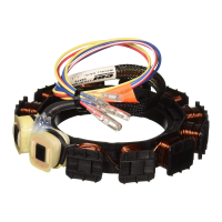
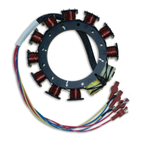
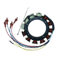
CDI P/N: 174-8778K 1
This unit replaces the following 2, 3, and 4 cylinder P/N's: 398-818535A 3, 5, 8, 9,10,13,14, 15, and 31; 398-8778A6, 10, 16, 17, 18, 21, 22,
23, 24, 25, 26, 27, 28, 29, and F749095.
Warning! This product is designed for installation by a professional marine mechanic. CDI Electronics cannot be held liable for
injury or damage resulting from improper installation, abuse, neglect, or misuse of this product.
It is recommended that dielectric grease (i.e. CDI 991-9705) be used in the bullet nose connectors to help prevent corrosion.
Any sign of leakage out of the high voltage coils or bubbling around the battery charge windings indicate a bad Stator. Check for burned
marks on each pole. If a problem is found on the battery windings, we recommend the Rectifier be closely checked. To replace Stators with
ring terminals, please use the fork terminals enclosed with this Stator.
If this Stator is to be used as a replacement for the Mercury “Red” Stator, connect all wires to the Switchbox in their designated
position. The Adapter Module used with the Red Stator is no longer needed.
If this Stator is to be used on a 3 cylinder engine, connect the Red/white and Blue/white striped wires to engine ground.
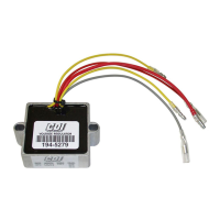
This Stator can be used with either a 9 amp Rectifier or a 16 amp Voltage Regulator.
INSTALLATION
1. Disconnect the Negative battery cable.
2. Disconnect the Stator wires from the Switchbox, engine ground, and the Rectifier.
3. Remove the flywheel according to the service manual for your engine.
4. Mark the position of the mounting screws in relation to where the Stator wires come out of the old Stator and remove the old Stator.
5. Orient and install the new Stator (using a good thread locker applied to the bolts) in the same position as the old Stator on the engine
and install the flywheel, following the service manual instructions.
6. Connect the Yellow wires from the Stator to the Rectifier, ignoring any stripes on the Regulator’s Yellow wires.
7. Connect the Stator leads as follows:
New Stator 2 Cylinder Switchbox 3 Cylinder Switchbox 4 Cylinder Switchbox
Red (High speed Coil) Red (High speed Coil) Red (High speed Coil) Red (High speed Coil)
Blue (Low speed Coil) Blue (Low speed Coil) Blue (Low speed Coil) Blue (Low speed Coil)
Red/White (High speed Coil) Red/White (High speed Coil) Engine Ground Red/White Stripe (High speed Coil)
Blue/White (Low speed Coil) Blue/White (Low speed Coil) Engine Ground Blue/White Stripe (Low speed Coil)
7. If this Stator is to be used on a 3 cylinder engine application, connect the Red/White and Blue/White striped wires to a known good
engine ground.
8. If using this Stator on an application that uses a Switchbox with stud connections, it will be necessary for you to remove the female
bullet connectors attached to the Blue, Blue/White, Red, and Red/White wires that are preinstalled from the factory and install the fork
terminals that come supplied in the kit provided with the Stator. Crimp or solder the fork connectors to the Blue, Blue/White, Red, and
Red/White wires.
9. If your engine used a Mercury Red Stator Kit, it is normal for that application to have NOT used the Red and the Red/White wire (or
Red and Red/White stud post on a studded Switchbox). These are usually either taped up or capped off. With the CDI Electronics 194-
8778K 1 Stator, the Red and Red/White wire WILL be used. Find the Red wire (or Red stud post on a studded Switchbox) and connect
the Solid Red wire from the New Stator to the Switchbox. On a 2 and 4 cylinder application, connect the Red/White wire to the
Switchbox in its appropriate place. On a 3 cylinder application, connect the remaining Red/White and Blue/White striped wires to a
known good engine ground.
10. Replace the flywheel according to the service manual.
11. Connect the Negative battery cable.