EasyManua.ls Logo

CDI 174-9610K 2 - User Manual

Default Icon
4 pages
Print Icon
To Next Page IconTo Next Page
Loading...
Installation and Troubleshooting Guide
This installation is to be completed by an Authorized Dealer or Professional Service
Technician. For questions regarding installation or warranty, call CDI Tech Support
at 866-423-4832. Do not return to the Dealer or Distributor where the part was purchased.
Contact CDI Electronics Directly for Return Material Authorization.
CDI Electronics, LLC 353 James Record Road SW Huntsville, AL 35824 USA
Web Support: www.cdielectronics.com Tech Support: 1-866-423-4832 Order Parts: 1-800-467-3371
All rights reserved. Reproduction or use of content, in any manner, without express written permission by CDI Electronics, LLC., is prohibited.
Rev D 6/19/2023 Page - 1 of 4 QF-358
CDI P/N: 174-9610K 2
This unit replaces the following P/Ns: 398-9610A 3, A 5, A 6, A 9, A14, A17, A19, A22, and A24.
Warning! This product is designed to be installed by a professional marine mechanic. CDI Electronics cannot be held liable for
injury or damage resulting from improper installation, abuse, neglect, or misuse of this product.
It is recommended that dielectric grease (i.e. CDI 991-9705) be used in the bullet nose connectors to help prevent corrosion.
Any sign of leakage out of the Ignition charge coils or bubbling around the battery charge windings indicate a bad Stator. Check for burned
marks on each pole. If a problem is found on the battery windings, we recommend the Voltage Regulator be closely checked. To replace
Stators with ring terminals, please use the bullet to ring adapters enclosed with this Stator.
INSTALLATION
To replace the 398-9610A 3, A 5, A 6, A 9, and A14 Stators with two Yellow leads:
1. Disconnect the Negative battery cable.
2. Disconnect the Stator wires from the Switchbox, engine ground, and the Voltage Regulator.
3. Remove the flywheel according to the service manual for your engine.
4. Mark the position of the mounting screws in relation to where the Stator wires come out of the old Stator.
5. Remove the old Stator.
6. Orient and install the new Stator (using a good thread locker applied to the bolts) in the same position as the old Stator on the engine
and install the flywheel, following the service manual instructions.
7. Install the jumper leads included with the new Stator to the Stator leads, matching the color sets (Solid Yellow and Yellow/Black Stripe).
8. Connect the Yellow stator leads to the Voltage Regulator.
9. Connect the Stator Black wire to engine ground.
10. Connect the Red and Blue wires to one Switchbox and the Red/White and Blue/White wires to the other Switchbox. It does not matter
which set of wires goes to which Switchbox.
11. Reconnect the Negative battery cable.
To replace the 398-9610A17, A19, A22, and A24 Stators with four Yellow leads:
1. Disconnect the Stator wires from the Switchbox, engine ground, and the Voltage Regulator.
2. Remove the flywheel according to the service manual for your engine.
3. Mark the position of the mounting screws in relation to where the Stator wires come out of the old Stator.
4. Remove the old Stator.
5. Orient and install the new Stator (using a good thread locker applied to the bolts) in the same position as the old Stator on the engine
and install the flywheel, following the service manual instructions.
6. Connect the Stator leads to the Voltage Regulator, matching the short Yellow Stator wires to one Voltage Regulator and the long
Yellow stator wires to the other Voltage Regulator.
7. Connect the Stator black wire to engine ground.
8. Connect the Red and Blue wires to one Switchbox and the Red/White and Blue/White wires to the other Switchbox. It does not matter
which set of wires goes to which Switchbox.
9. Reconnect the Negative battery cable.
TROUBLESHOOTING
NO SPARK ON ANY CYLINDER:
1. Perform a visual inspection of the Stator and Trigger wiring to the Switchbox. Check to make sure that the wiring is correct, clean, and
free of corrosion, and that all connections are tight.
2. Disconnect the Black/Yellow kill wire AT THE SWITCHBOXES and retest. If the engine’s Ignition now has spark, the stop circuit has a
fault. Check the key switch, harness, and shift switch (if present).
3. Disconnect the Yellow wires from the Stator to the Voltage Regulator and retest. If the engine now has spark, replace the Voltage
Regulator.
4. Check the cranking RPM. A cranking speed less than 250 RPM will not allow the system to spark properly. This can be caused by a
weak battery, dragging starter, bad battery cables, or a mechanical problem inside the engine.
5. Inspect the flywheel Charge coil and Trigger magnets to see if they are loose or broken.
Question and Answer IconNeed help?

Do you have a question about the CDI 174-9610K 2 and is the answer not in the manual?

Summary

Installation

Troubleshooting

No Spark on Any Cylinder

Steps to diagnose and resolve the absence of spark on any cylinder of the engine.

No Spark on One Bank

Troubleshooting steps for engines with no spark on one bank of cylinders (odd or even).

No Spark or Intermittent Spark

Diagnosing and fixing issues with no spark or inconsistent spark on one or more cylinders.

Will Not Accelerate

Troubleshooting engine performance issues when it fails to accelerate beyond 3000-4000 RPM.

Destroyed Cylinders;Pistons

Procedures for diagnosing engine damage, specifically one or two cylinders/pistons.

Miss at Any RPM

Steps to identify and fix engine misfires that occur at any engine speed.

No Spark with Sparkplugs Installed

Troubleshooting steps when spark is absent despite sparkplugs being installed.

Engine Will Not Run

Diagnosing why an engine fails to run even when spark is present on all cylinders.

Will Not Idle Below 1500 RPM

Troubleshooting engine issues preventing it from idling below 1500 RPM.

Engine Will Not Stop (Kill)

Steps to diagnose and fix issues where the engine cannot be shut off using the kill switch.

Battery Charging Issues

Guidance on troubleshooting problems related to the outboard's battery charging system.

Tachometer Tests

Procedures for testing the tachometer signal and its associated components.

Overview

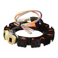
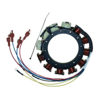
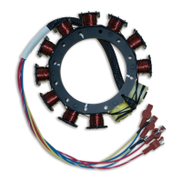
The CDI P/N: 174-9610K 2 is an electronic stator designed as a replacement for various P/N's including 398-9610A 3, A5, A6, A 9, A14, A17, A19, A22, and A24. This device is intended for marine applications and is crucial for the proper functioning of an outboard engine's ignition and charging systems. It is designed to be installed by a professional marine mechanic, and CDI Electronics explicitly states that they cannot be held liable for injury or damage resulting from improper installation, abuse, neglect, or misuse of the product.

Function Description:

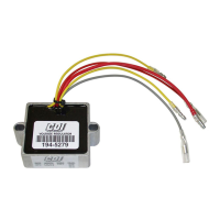
The stator is a key component in an engine's electrical system, primarily responsible for generating electrical current for both the ignition system and battery charging. It consists of various coils (charge coils and trigger magnets) that produce voltage as the flywheel rotates around them. The generated voltage is then routed to other components like the switchbox, voltage regulator, and engine ground to power the ignition coils and recharge the battery. The 174-9610K 2 specifically replaces stators with either two or four yellow leads, indicating different configurations for voltage regulation and charging. The device includes jumper leads for proper connection to the stator leads, ensuring correct color matching (Solid Yellow and Yellow/Black Stripe).

Important Technical Specifications:

The manual provides detailed resistance and DVA (Diode Voltage Adapter) readings for various stator and trigger coil connections, which are critical for troubleshooting and verifying the stator's health. These specifications are given for both OEM and CDI components, as well as for connected and disconnected states, allowing for comprehensive diagnostic testing.

  • Low Speed Coil (Blue/Blue-White to Engine Gnd):
    • OEM Ohms: 5.0-7.0K Ω
    • CDI Ohms: 2.0-2.5K Ω
    • DVA (Connected/Disconnected): 140 V Minimum
  • High Speed Coil (Red/Red-White to Engine Gnd):
    • OEM Ohms: 90-200 Ω
    • CDI Ohms: 28-36 Ω
    • DVA (Connected/Disconnected): 20 V Minimum
  • Trigger Coils (Brown/White/Purple to other Trigger Wires):
    • OEM Ohms: 0.8-1.4K Ω
    • CDI Ohms: 0.8-1.4K Ω
    • DVA (Connected/Disconnected): 4 V Minimum
  • Trigger Coils (Brown/White/Purple to Engine Gnd):
    • OEM Ohms: Open
    • CDI Ohms: Open
    • DVA (Connected/Disconnected): 1 V Minimum

These values are essential for diagnosing issues such as no spark, intermittent spark, or problems with acceleration and idling. For instance, a sharp drop in DVA on the blue or red wires often indicates a bad stator.

Usage Features:

The installation process involves several steps, including disconnecting the negative battery cable, removing the flywheel, and carefully positioning the new stator. Dielectric grease (CDI 991-9705) is recommended for bullet nose connectors to prevent corrosion. The stator comes with bullet-to-ring adapters for compatibility with older ring terminal configurations.

  • For 398-9610A 3, A5, A6, A 9, and A14 Stators (two Yellow leads):
    • Connect Yellow stator leads to the Voltage Regulator.
    • Connect the Stator Black wire to engine ground.
    • Connect Red and Blue wires to one Switchbox, and Red/White and Blue/White wires to the other Switchbox.
  • For 398-9610A17, A19, A22, and A24 Stators (four Yellow leads):
    • Connect short Yellow Stator wires to one Voltage Regulator and long Yellow stator wires to the other Voltage Regulator.
    • Connect the Stator black wire to engine ground.
    • Connect Red and Blue wires to one Switchbox, and Red/White and Blue/White wires to the other Switchbox.

Maintenance Features (Troubleshooting and Diagnostics):

The manual provides extensive troubleshooting guides for various engine problems, emphasizing the stator's role in each.

  • No Spark on Any Cylinder:
    • Visual inspection of wiring for corrosion and tightness.
    • Disconnecting the Black/Yellow kill wire to check for stop circuit faults.
    • Disconnecting Yellow wires from the stator to the voltage regulator; if spark returns, replace the voltage regulator.
    • Checking cranking RPM (should be >250 RPM).
    • Inspecting flywheel charge coil and trigger magnets for looseness or breakage.
    • Checking stator and trigger resistance and DVA readings against specified values.
    • Disconnecting Red and Red/White wires; if spark returns, the switchbox is likely bad.
  • No Spark on One Bank (Odd or Even Cylinders):
    • Similar checks as "No Spark on Any Cylinder," with an emphasis on swapping stator wires and switchboxes to isolate the fault. If the problem moves with the stator wires, replace the stator; if it stays with a switchbox, replace the switchbox (both switchboxes recommended as a set).
  • No Spark or Intermittent Spark on One or More Cylinders:
    • Checking bias circuitry by disconnecting the White/Black wire between switchboxes.
    • Checking DVA on green wires from the switchbox to ignition coils (should be >150 DVA).
    • Using a spark gap tester and inductive tachometer to identify misfiring cylinders.
    • Rotating the stator one bolt hole in either direction to see if the miss resolves.
  • Will Not Accelerate Beyond 3000-4000 RPM:
    • Disconnecting Yellow wires from the stator to the voltage regulator; if spark improves, replace the voltage regulator.
    • Disconnecting the Idle Stabilizer (advance module) and resetting timing.
    • Checking DVA on blue and red stator wires for sudden drops at high RPM.
  • Miss at Any RPM:
    • Disconnecting Yellow wires from the stator to the regulator/rectifier; if miss clears, replace the regulator/rectifier.
    • Disconnecting the Idle Stabilizer.
    • Checking DVA on green wires from the switchbox to ignition coils (should be 150-400 DVA max).
    • Checking DVA on blue and red stator wires for sudden drops.
    • Performing a high-speed shutdown and reading spark plugs for water.
    • Inspecting flywheel magnets.
    • Rotating the stator one bolt hole.
  • No Spark with Sparkplugs Installed:
    • Checking for dragging starter or low battery.
    • Disconnecting the voltage regulator.
  • Spark on All Cylinders But Engine Will Not Run:
    • Checking ignition timing for #1 cylinder and all cylinders.
    • Checking resistance on each switchbox's White/Black wire (13-15K Ω).
  • Will Not Idle Below 1500 RPM:
    • Checking bias resistance from the Black/White terminal on the switchbox (13-15K Ω).
    • Checking stator and trigger resistance and DVA.
    • Checking for air leaks.
  • Destroyed One or Two Cylinders/Pistons:
    • Checking bias resistance from the Black/White terminal on the switchbox (13-15K Ω). Readings outside this range indicate a defective switchbox, and both switchboxes should be replaced as a set due to potential "domino effect."
    • Using an analog DVA meter to check voltage on the White/Black (Bias) terminal for fluctuations.
  • Engine Will Not Stop (Kill):
    • Disconnecting the Black/Yellow (or Orange) wire(s) at the switchbox and shorting to engine ground. If this stops spark, the stop circuit has a fault; otherwise, replace the switchbox.
  • Battery Charging Issues:
    • Emphasizes battery type: single (NOT more than one) 850+ CCA dual purpose or cranking/starting non-maintenance-free battery. Maintenance-free batteries are strongly discouraged for outboard use.
    • Checking battery connections for tightness and corrosion.
    • Measuring DVA across the stator's yellow battery charge wire pairs (8-25 DVA at idle connected, 17-50 DVA at idle disconnected). Low voltage or signs of browning/varnish dripping on the stator indicate a faulty stator.
  • Tachometer Tests:
    • Measuring DVA across the stator's yellow battery charge wire pairs.
    • Disconnecting the voltage regulator's gray wire and checking DVA (should be >8 DVA at 800-1000 RPM).
    • Running a jumper wire from the gray wire to one of the stator's yellow wires.
    • Trying a known good tachometer. If still no signal, replace the stator.

The manual stresses the importance of using a DVA meter for accurate diagnostics and provides specific voltage ranges for various components. It also highlights the need for proper battery selection and maintenance to prevent charging issues.

CDI 174-9610K 2 Specifications

General IconGeneral
BrandCDI
Model174-9610K 2
CategoryMarine Equipment
LanguageEnglish

Related product manuals