Installation and Troubleshooting Guide
This installation is to be completed by an Authorized Dealer or Professional Service
Technician. For questions regarding installation or warranty, call CDI Tech Support
at 866-423-4832. Do not return to the Dealer or Distributor where the part was purchased.
Contact CDI Electronics Directly for Return Material Authorization.
CDI Electronics, LLC • 353 James Record Road SW • Huntsville, AL 35824 USA
Web Support: www.cdielectronics.com • Tech Support: 1-866-423-4832 • Order Parts: 1-800-467-3371
All rights reserved. Reproduction or use of content, in any manner, without express written permission by CDI Electronics, LLC., is prohibited.
Rev D • 6/19/2023 Page - 2 of 4 QF-358
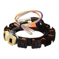
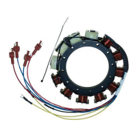
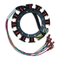
6. Check Stator and Trigger resistance and DVA:
Read from Read to OEM Ohms CDI Ohms DVA (Connected) DVA Disconnected
Blue (Low speed coil) Engine Gnd 5.0-7.0K Ω 2.0-2.5K Ω 140 V Minimum 140 V Minimum
Blue/White (Low speed coil) Engine Gnd 5.0-7.0K Ω 2.0-2.5K Ω 140 V Minimum 140 V Minimum
Red (High speed coil) Engine Gnd 90-200 Ω 28-36 Ω 20 V Minimum 20 V Minimum
Red/White (High speed coil) Engine Gnd 90-200 Ω 28-36 Ω 20 V Minimum 20 V Minimum
Brown (#1 Trigger) (a) White (#4 Trigger) (b) 0.8-1.4K Ω 0.8-1.4K Ω 4 V Minimum 4 V Minimum
White (#3 Trigger) (a) Purple (#6 Trigger) (b) 0.8-1.4K Ω 0.8-1.4K Ω 4 V Minimum 4 V Minimum
Purple (#5 Trigger) (a) Brown (#2 Trigger) (b) 0.8-1.4K Ω 0.8-1.4K Ω 4 V Minimum 4 V Minimum
Brown (#1 Trigger) (a) Engine Gnd Open Open 1 V Minimum -
White (#3 Trigger) (a) Engine Gnd Open Open 1 V Minimum -
Purple (#5 Trigger) (a) Engine Gnd Open Open 1 V Minimum -
Brown (#2 Trigger) (b) Engine Gnd Open Open 1 V Minimum -
White (#4 Trigger) (b) Engine Gnd Open Open 1 V Minimum -
Purple (#6 Trigger) (b) Engine Gnd Open Open 1 V Minimum -
(a) Black band – Inside Switchbox (Engines using Studded Switchboxes)
(b) Yellow band – Outside Switchbox (Engines using Studded Switchboxes)
7. Disconnect Red and Red/White wires and retest. If the ignition system now has spark, the Switchbox is usually bad.
NO SPARK ON ONE BANK (ODD OR EVEN CYLINDERS ON INLINE 6 CYLINDER):
1. Perform a visual inspection of the Stator and Trigger wiring to the Switchbox. Check to make sure that the wiring is correct, clean, and
free of corrosion, and that all connections are tight.
2. Disconnect the Black/Yellow kill wire AT THE SWITCHBOXES and retest. If the engine’s Ignition now has spark, the stop circuit has a
fault. Check the key switch, harness, and shift switch (if present).
3. Disconnect the Yellow wires from the Stator to the Voltage Regulator and retest. If the engine now has spark, replace the Voltage
Regulator.
4. Check the cranking RPM. A cranking speed less than 250 RPM will not allow the system to spark properly. This can be caused by a
weak battery, dragging starter, bad battery cables, or a mechanical problem inside the engine.
5. Check the resistance and DVA of the Stator (see NO SPARK ON ANY CYLINDER).
6. Swap both sets of the Stator wires between the Switchboxes. If the problem moves, replace the Stator. If the problem stays on the
same bank, swap physical location and all connections of the two Switchboxes. If the problem stays with one Switchbox, replace the
Switchbox.
NOTE: If the Switchbox is bad, it is recommended that BOTH Switchboxes be replaced AS A SET.
NO SPARK OR INTERMITTENT SPARK ON ONE OR MORE CYLINDERS:
1. Perform a visual inspection of the Stator and Trigger wiring to the Switchbox. Check to make sure that the wiring is correct, clean, and
free of corrosion, and that all connections are tight.
2. Disconnect the White/Black wire between the Switchboxes and retest. If all cylinders now have spark, replace both Switchboxes as
there is a problem in the Bias circuitry.
3. Check the resistance and DVA of the Stator and Trigger (see NO SPARK ON ANY CYLINDER).
4. Check the DVA on the Green wires from the Switchbox while connected to the Ignition coils. Check the reading on the Switchbox
terminal AND on the Ignition coil terminal. You should have a reading of at least 150 DVA or more at both terminals. If the reading is
low on one cylinder, disconnect the Green wire from the Ignition coil for that cylinder and reconnect it to a Pack Load Resistor. Retest. If
the reading is now good, the Ignition coil is likely bad. A continued low reading symptom indicates a bad Switchbox.
5. Connect a spark gap tester and verify which cylinders are misfiring. If the cylinders are only misfiring above an idle, connect an
inductive tachometer to all cylinders and try to isolate the problem cylinders.
6. Disconnect the Yellow wires from the Stator to the Voltage Regulator and retest. If the engine now has spark, replace the Voltage
Regulator.
7. Check the cranking RPM. A cranking speed less than 250 RPM will not allow the system to fire properly. This can be caused by a weak
battery, dragging starter, bad battery cables, or a mechanical problem inside the engine.
WILL NOT ACCELERATE BEYOND 3000-4000 RPM:
1. Disconnect the Yellow wires from the Stator to the Voltage Regulator and retest. If the engine now has good spark, replace the Voltage
Regulator.
2. Disconnect the Idle Stabilizer (advance module) and reset the timing according to the service manual for your engine. If the problem
clears, discard the Idle Stabilizer as it is not needed.
 Loading...