Do you have a question about the CDVI RADIUM WRW and is the answer not in the manual?
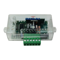
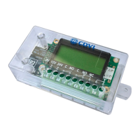
Diagram illustrating terminal connections for the receiver, including power, data, and antenna.
Detailed explanation of each terminal pin function on the receiver, from P1 to antenna connections.
Description of the WRW receiver, its operating frequency, and output signal format.
Lists key technical specifications including frequency, power, current, output type, temperature, dimensions, and weight.
Images and labels of compatible remote models: R1, R2, and R4.
Explains how remote data is transmitted and stored, and the receiver's capacity for combinations.
Illustrates where to find the Facility Code (FC) and Serial Number (SN) on a remote.
Step-by-step instructions to disable facility code verification using the P1 button and L2 LED.
Step-by-step instructions to restore facility code verification using the P1 button and L2 LED.
Explains the meaning of L2 LED flashes for valid and invalid signal reception.
Procedure to erase receiver memory and reset all settings to factory default using P1 and L2 LED.
Guidance on placing the receiver away from interference sources for optimal system performance.
Details the 60-month warranty period and conditions for repair or substitution.
The CDVI Radium WRW is a superheterodyne wireless receiver designed for indoor use, operating at 433.92 MHz in AM/ASK. It is engineered to integrate seamlessly with access control systems by providing a Wiegand 26-bit output signal. This receiver is a key component in systems that utilize remote controls for access, translating the remote's signals into a format compatible with standard access control panels.
The core function of the WRW receiver is to receive signals from compatible remote controls and convert them into a Wiegand 26-bit output. This output typically includes the Facility Code and the Serial Number of the remote, which are essential for identifying authorized users within an access control system. The receiver does not transmit information about the specific button pressed on the remote within the Wiegand signal.
The device is composed of a main board that houses power supply and output connectors, and an RF (Radio Frequency) card responsible for signal reception. It supports a wide range of power inputs (12 or 24 Vac/dc), making it versatile for various installations.
A crucial aspect of the WRW's operation is its ability to store up to 50 different combinations of "Facility code - Button type." This means it can differentiate between various facility codes and specific buttons (A, B, C, D) on the remotes. For example, it can store combinations like "001-A" or "002-B," allowing for granular control over access permissions. However, it does not support combinations of multiple buttons pressed simultaneously, such as "A+B" or "C+D."
The receiver features two LED indicators: L1 (Green) for power supply and L2 (Red) for programming and status feedback. A programming button (P1) is used to initiate various setup and maintenance procedures. The device also includes connections for an external antenna, which can be a supplied antenna or a tuned SEA433 antenna for enhanced reception.
The WRW receiver offers several features that enhance its usability and integration into access control systems:
Remote Button Programming: To authorize a remote, the user presses the P1 button until the L2 LED turns on, then presses a key button on the remote. The L2 LED will then turn off and flash briefly, indicating successful programming. If an operation is not allowed (e.g., memory is full or the code is already stored), the L2 LED will flash twice quickly.
Facility Code Verification: The receiver can be configured to verify the facility code transmitted by the remote. By default, it accepts only remotes with the correct manufacturer key and, once initialized, outputs the remote's serial number and facility code.
Disabling Facility Code Verification: For installations where facility code verification is not desired, this feature can be disabled. To do so, the user presses P1 until L2 turns on, then releases and presses P1 again within 1 second. The L2 LED will blink for 5 seconds and then turn off, indicating that facility code verification is disabled. When disabled, the receiver will accept any facility code while still checking the key button. This function can only be performed if at least one remote button has been authorized.
Restoring Facility Code Verification: To re-enable facility code verification, the user presses P1 until L2 turns on and starts blinking, then releases and presses P1 again within 1 second. The L2 LED will remain steady for 5 seconds and then turn off, confirming that facility code verification is restored. This function also requires the receiver to have been initialized with at least one authorized remote button.
LED Indicators for Signal Reception: The L2 LED provides visual feedback on signal reception. A 1-second flash indicates a valid signal, while a quick flash signifies an invalid signal.
Compatibility with Various Remotes: The receiver is compatible with 1-button, 2-button, and 4-button remotes, including those with built-in CDVI or HID proximity badges, offering flexibility in remote control choices.
Indoor Enclosure: The appliance is housed in an indoor enclosure, protecting its internal components from environmental factors typically found indoors.
The WRW receiver includes a memory reset function that allows the user to restore the device to its factory default settings, effectively erasing all stored remote codes and configurations.
Memory Reset (Factory Default): To perform a memory reset, the user presses P1 until the L2 LED turns on, then releases P1 and presses it again until L2 flashes three times. This procedure erases all settings and returns the receiver to its original factory state.
Optimal Placement Considerations: For optimal system performance, it is crucial to place the receiver away from interference sources such as magnetic fields, radio emissions from neon ballasts, or electric motors. Performing range tests before permanent mounting is recommended to ensure quality signal reception.
The device is designed for long-term reliability, backed by a 60-month warranty from the manufacturer's date, covering defects in components. After-sale service is provided directly by the factory.
| Technology | Radio |
|---|---|
| Frequency | 433.92 MHz |
| Channels | 2 |
| Current Consumption | 30 mA |
| Output Type | Relay |
| Power supply | 12-24V AC/DC |
| Operating Voltage | 12/24Vac/dc |