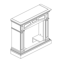
This document provides assembly instructions and product information for the Cedar Ridge Hearth Wood Fireplace Mantel, model #CRHFD400RT-M-M.
Function Description:
The Cedar Ridge Hearth Wood Fireplace Mantel is designed to house and display a fireplace insert, creating a decorative and functional focal point in a room. It can be assembled for either a standard wall installation or a corner installation, offering versatility in placement. The mantel provides a sturdy frame for the fireplace insert and enhances the aesthetic appeal of the living space.
Important Technical Specifications:
- Item Number: #0328248
- Model Number: CRHFD400RT-M-M
- Dimensions (Standard Installation):
- Width: 44.52 inches
- Depth: 16.18 inches (top surface), 21.53 inches (base)
- Height: 42.83 inches
- Estimated Assembly Time: 60 minutes
- Tools Required for Assembly: Philips Screwdriver, Flathead Screwdriver, Drill, Tape Measure.
Package Contents (Parts List):
The mantel consists of various wooden panels and supports, along with hardware for assembly.
- A: Top (Quantity: 1)
- B: Panel (Quantity: 1)
- C: Left Upper Panel (Quantity: 1)
- D: Right Upper Panel (Quantity: 1)
- E: Left Lower Panel (Quantity: 1)
- F: Right Lower Panel (Quantity: 1)
- G: Base (Quantity: 1)
- H: Top Triangle Panel (Quantity: 1) - Used for corner installation
- I: Backboard (Quantity: 2)
- J: Set Square Support (Quantity: 1) - Used for corner installation
Hardware Contents:
- AA: Cam Dowel (Quantity: 16) - PCAM-023
- BB: Cam Lock (Quantity: 16) - PCAM-023
- CC: Wall Anchor (Quantity: 2) - ML066-01
- DD: ST4 Screw 1 3/16 in. (Quantity: 20) - GB/T 951 - 4 x 30
- EE: ST5 Screw 2 3/8 in. (Quantity: 2) - GB/T950 - 5 x 60
- FF: ST4 Screw 5/8 in. (Quantity: 18) - GB/T 951 - 4 x 16
- GG: Mounting Bracket (Quantity: 3) - SJ 002
- HH: White Key (Quantity: 1) - ML067-01
- II: ST4 Screw 1 9/16 in. (Quantity: 8) - GB/T 951 4 x 40
- JJ: M6 Screw 1 3/8 in. (Quantity: 4) - GB/T 818 6 x 35
- Hardware Package: HP007
Usage Features:
The assembly process is detailed with step-by-step instructions and corresponding diagrams.
- Frame Assembly: The Left Upper Panel (C) and Left Lower Panel (E) are fastened together using M6 Screws (JJ). The same process applies to the Right Upper Panel (D) and Right Lower Panel (F).
- Panel Attachment: Cam Locks (BB) are inserted into Panel (B), and Cam Dowels (AA) are screwed into the Left Upper Panel (C) and Right Upper Panel (D). Panel (B) is then attached to the assembled frame (C, D, E, F) by tightening the Cam Locks (BB).
- Base Attachment: Cam Locks (BB) are inserted into the Left Lower Panel (E) and Right Lower Panel (F). Cam Dowels (AA) are screwed into the Base (G). The Base (G) is then attached to the assembled frame (B, C, D, E, F) by tightening the Cam Locks (BB).
- Batten to Base: A batten is fastened to the Base (G) using ST4 Screws 1-9/16 in. (II).
- Top Attachment: Cam Locks (BB) are inserted into Panel (B), the Left Upper Panel (C), and the Right Upper Panel (D). Cam Dowels (AA) are screwed into the Top (A). The Top (A) is then attached to the assembled frame (B, C, D, E, F) by tightening the Cam Locks (BB).
- Batten to Top: A batten is fastened to the Top (A) using ST4 Screws 1-9/16 in. (II).
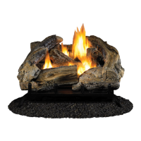
- Insert Installation: After the mantel is assembled, it is lifted upright, and the fireplace insert is pushed into the mantel from the front.
- Positioning: The fireplace is then positioned in the desired location.
Corner Mantel Installation (Optional):
For corner installations, specific steps are added after the initial frame assembly.
9. Top Triangle Panel Attachment: The Top (A) Panel is turned over. Mounting Brackets (GG) are used to connect the Top (A) to the Top Triangle Panel (H) with ST4 Screws 5/8 in. (FF).
10. Top Assembly (Corner): Cam Locks (BB) are inserted into Panel (B), the Left Upper Panel (C), and the Right Upper Panel (D). Cam Dowels (AA) are screwed into the Top (A). The Top (A) is then attached to the assembled frame (B, C, D, E, F) by tightening the Cam Locks (BB).
11. Batten to Top (Corner): A batten is fastened to the Top (A) using ST4 Screws 1-9/16 in. (II).
12. Backboard Attachment: The left and right Backboard (I) trim pieces are attached to the back of the fireplace with ST4 Screws 1-3/16 in. (DD).
13. Insert Installation (Corner): After the mantel is assembled, it is lifted upright, and the fireplace insert is pushed into the mantel from the front.
14. Wall Anchoring (Corner): Two holes (5/16 in.) are drilled in the corner where the fireplace will be displayed: one at 39 5/16 in. from the ground up, and the second at 41 ½ in. from the ground up. Wall Anchors (CC) are inserted into these holes by pinching the anchor tabs together.
15. Set Square Support Attachment (Corner): A triangular wood block is attached to the drilled holes using ST4 Screws 2 3/8 in. (EE). This block supports the Set Square Support (J). For thin walls, a White Key (HH) is inserted into the wall anchor and pushed to "pop" open the anchor wings.
16. Final Positioning (Corner): The fireplace is pushed into the corner so that the Top Triangle Panel (H) rests on top of the Set Square Support (J).
Maintenance Features:
- Warnings and Cautions:
- Overtightening Screws: Avoid overtightening screws to prevent stripping threads. A hand-powered screwdriver is recommended over a power screwdriver.
- Forcing Screws: Do not force screws into holes.
- Corner Installation (Baseboards): For corner installations, if baseboards are present where the fireplace is intended, the fireplace may not fit flush against the wall. Part of the baseboard molding may need to be removed for a proper flush fit.
- Replacement Parts:
- Only original replacement parts should be used to maintain warranty coverage.
- Customer service can be contacted at 1-866-573-0674 (8:00 a.m. - 4:30 p.m., EST, Monday - Friday) or via email at customerservice@usaprocom.com for parts under warranty or not under warranty.
- When calling for parts under warranty, be prepared to provide: your name, address, model and serial number of the heater, how the heater was malfunctioning, type of gas used (Propane/LP or Natural gas/NG), and purchase date. Defective parts may need to be returned to the factory.
- When calling for parts not under warranty, be prepared to provide: model number of your heater and the replacement part number.
- 2-Year Limited Warranty: The manufacturer warrants the product to be free from defects in workmanship and material for two (2) years from the date of purchase. This warranty applies only to the original purchaser.
- Warranty Service: To obtain warranty service, contact customer service at 1-866-573-0674. Proof of purchase (sales receipt copy) may be required.
- Exclusions: Costs of removal and reinstallation are the purchaser's responsibility. Damage due to accident, misuse, improper installation, or affixing non-manufacturer accessories is the purchaser's responsibility. The manufacturer assumes no responsibility for installation during the warranty period.
- Disclaimer: There are no further expressed warranties. The manufacturer disclaims all implied warranties and is not liable for incidental, consequential, or special damages, except as accorded by law. This warranty provides specific legal rights, and other rights may vary by state. This warranty supersedes all prior warranties.