19 support@cedarsummitplay.com
DWG. NO.
SCALE:1:50
Details
WEIGHT:
SIZE
SHEET 1 OF 3
REV.
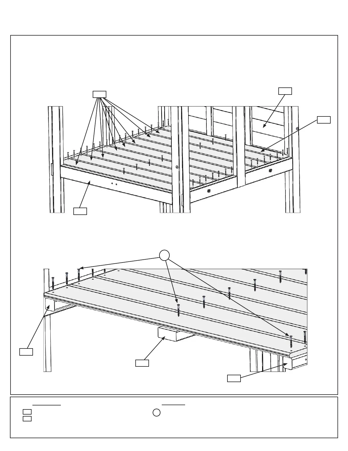
Use 5- #8 x 1½" Wood Screws per board to attach 1- Floor Board 1 x4
then attach 8 - Floor Board 1 x5 to the fort joists.
Space boards prior to fastening.
C: Starting at (2627) SW Wall Panel place (2648) Floor Board followed by 8 (2609) Floor Boards. Make sure all
boards are evenly spaced then attach to (2608) Floor Joist and each (2610) Side Joist with 5 (S20) #8 x 1-3/8”
Wood Screws per board. (g. 3.6 and 3.7)
Step 3: Floor Assembly
Part 3
1 x Floor Board 1 x 4 x 40-5/8”
8 x Floor Board 1 x 5 x 40-5/8”
2648
Wood Parts
Fig. 3.6
2627
Fig. 3.7
2622
Hardware
Panel removed
for clarity
2608
2610
2648
2609
45 x #8 x 1-3/8” Wood Screw
x 5 per
board
2610
2609
S20
S20