EasyManua.ls Logo

Cedrat Technologies CCBu40 - VIII.1. Interface with the Client; Supervisor

Cedrat Technologies CCBu40
32 pages
Print Icon
To Next Page IconTo Next Page
To Previous Page IconTo Previous Page
Loading...
16 / 32
CCBU40 COMPACT CONTROLLER BOARD - PRODUCT AND WARRANTY INFORMATION Version 1.21
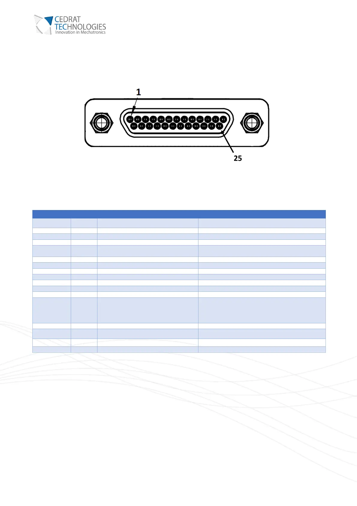
VIII.1. INTERFACE WITH THE CLIENT / SUPERVISOR
For the interface of the CCBu40 with the client supervisor, the connector is a micro D-Sub25.
Figure 4 : Supervisor interface
Pin N°
Signal
Description
1
SY
Analog sensor output for Y axis
±10V output.
2
SX
Analog sensor output for X axis
±10V output.
3
AIX
Analog order input for X axis
±10V input.
4
AIY
Analog order input for Y axis
±10V input.
5
T°C
Mechanism analogue temperature output
0-3.3V output. Only valid if PT1000 is used on the
mechanism.
6
Enable
Digital enable input
0-3.3V input. Referenced to GND
7
Fault
Digital fault output
0-3.3V output. Referenced to GND
8, 20
NC
9
RTS-
Negative Request To Send
RS422 signal
10
RTS+
Positive Request To Send
RS422 signal
11
RX-
Negative Receive
RS422 signal
12
RX+
Positive Receive
RS422 signal
13, 14, 15, 16,
17, 18, 19, 21
GND
Ground
22
TX+
Positive Transmit
RS422 signal
23
TX-
Negative Transmit
RS422 signal
24
CTS+
Positive Clear To Send
RS422 signal
25
CTS-
Negative Clear To Send
RS422 signal