18 / 32
CCBU40 COMPACT CONTROLLER BOARD - PRODUCT AND WARRANTY INFORMATION Version 1.21
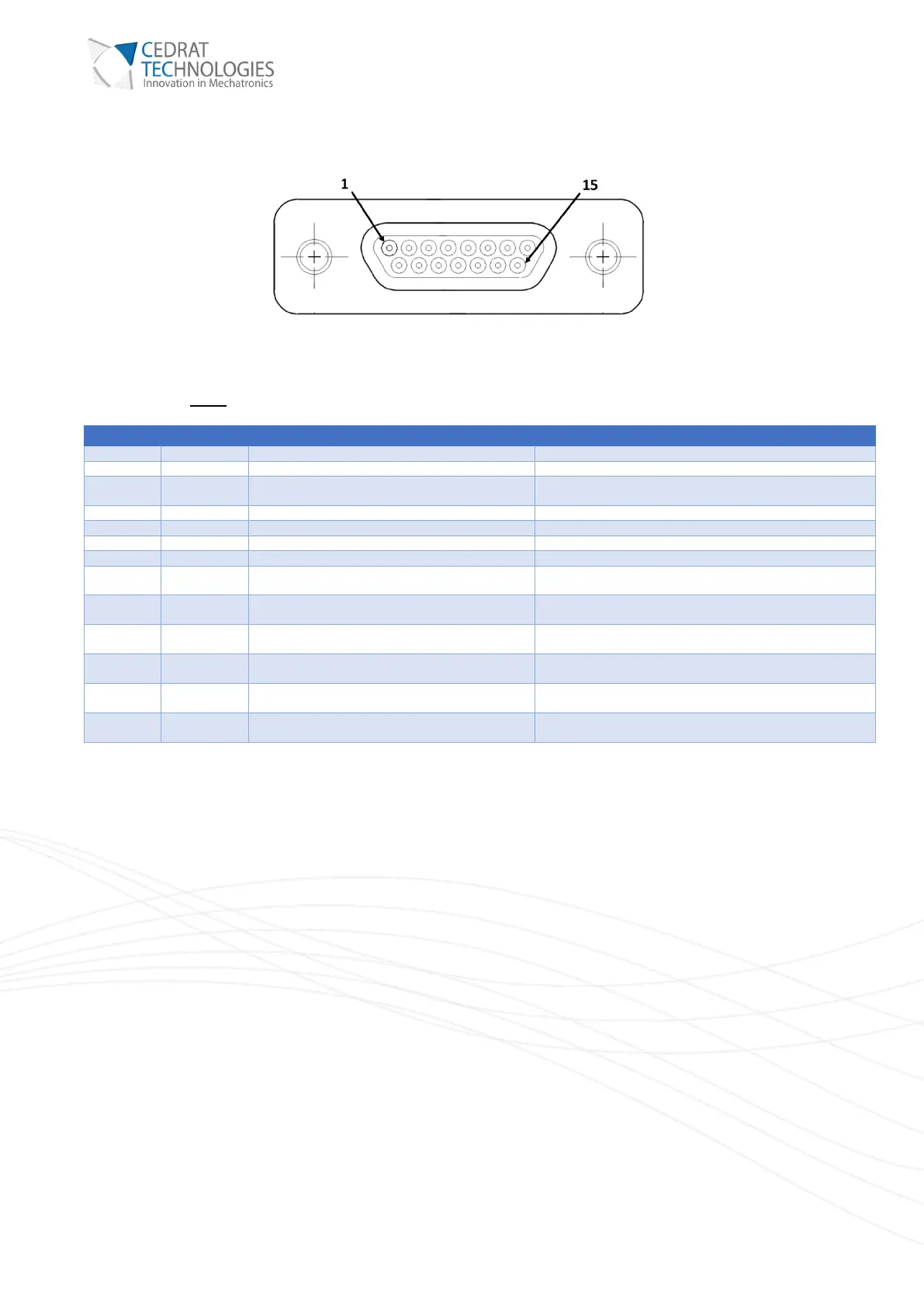
II) SENSOR CONNECTOR
Figure 7. Micro D-Sub 15 connector.
This connector must be connected to the mechanism.
+5V voltage reference for supplying the two SG
bridges
This voltage supplies two full SG bridges of 350Ω. Max
current is 30mA.
Positive middle node for the Y axis SG bridge
Voltage increases when the displacement on the Y axis
increases.
Negative middle node for the Y axis SG bridge
Voltage decreases when the displacement on the Y axis
increases.
Temperature signal from the integrated
temperature probe
Optional: can be connected to a PT1000 temperature probe
located on the mechanism.
Negative middle node for the X axis SG bridge
Voltage decreases when the displacement on the X axis
increases.
Positive middle node for the X axis SG bridge
Voltage increases when the displacement on the X axis
increases.
1-wire bus for EEPROM memory
Optional: can be connected to a DS2431 EEPROM located
on the mechanism.
Warning: The analog output signals “SX”, “SY”, have a 1kΩ output impedance and “T°C” has a 20kΩ
output impedance for protection. If used, they should be monitored with high input impedance device,
or the series output impedance should be considered.
VIII.1. EARTHING INTERFACE
The CCBu40 must be connected to ground / earth using the ground interface.This is an M3 interface, for a ring
cable lug.