17 / 32
CCBU40 COMPACT CONTROLLER BOARD - PRODUCT AND WARRANTY INFORMATION Version 1.21
VIII.2. POWER SUPPLY CONNECTOR
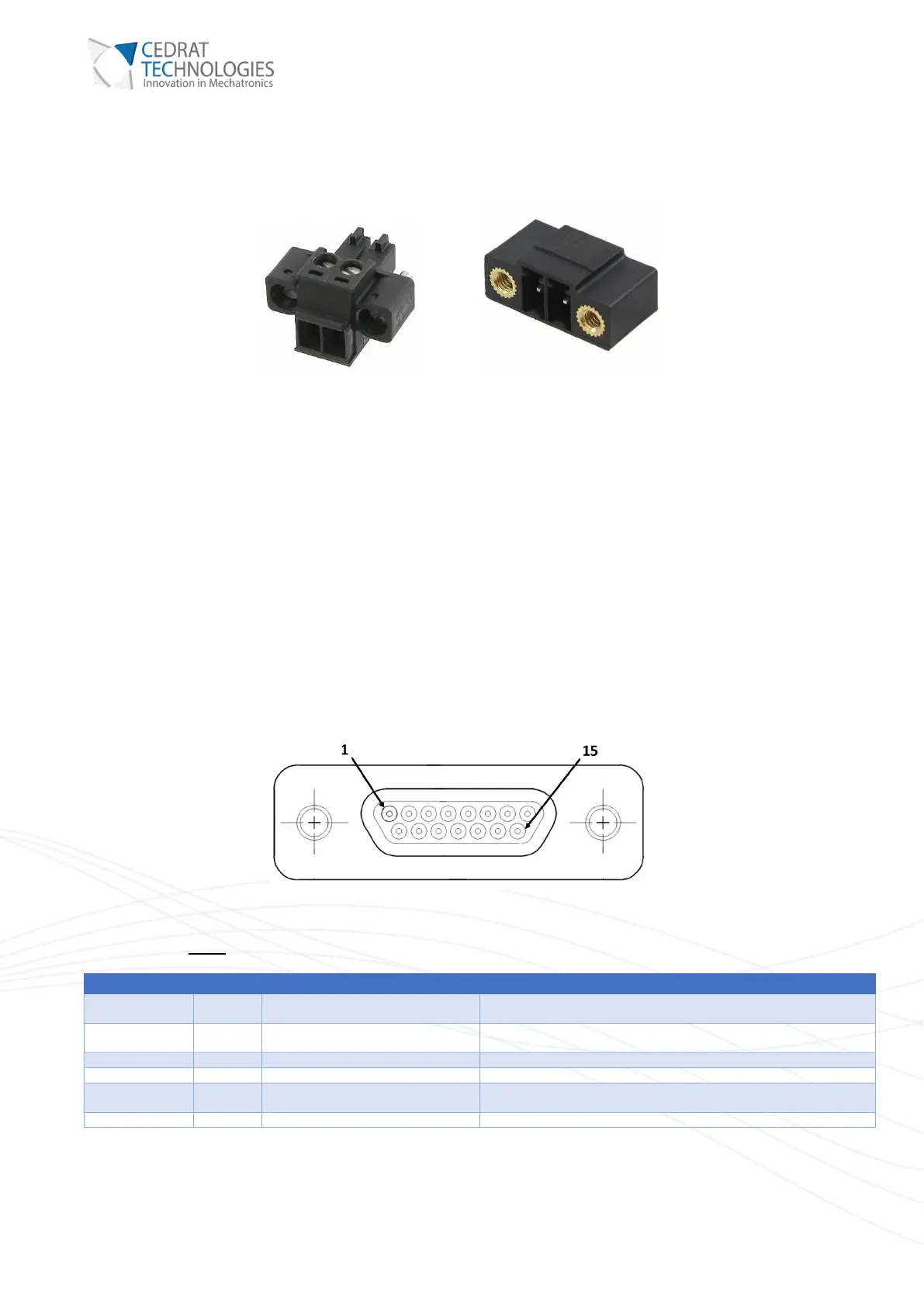
Figure 5. CCBU40’s Supply connector and its mating connector (Phoenix Contact: 1714977).
The pin 1 (on the left of the connector) must be connected to the 0V and the pin 2 (on the right) must be
connected to the +28V.
Note:
• The polarity is also printed on the front panel.
• The 0V must not be connected to the GND of the supervisor connector.
VIII.3. INTERFACE WITH THE PIEZO MECHANISM
I) ACTUATOR CONNECTOR (POWER)
Figure 6. Micro D-Sub 15 connector
This connector must be connected to the mechanism. It transmits the power to the actuators of the mechanism.
Thanks to this pin, the controller checks if a load is connected before
allowing the high voltage on the connector.