Page 11For technical questions, please call 1-888-866-5797.Item 59410
SAFETYOPERATIONMAINTENANCE SETUP
Continuity Measurement
Test continuity between two
points of a circuit.
WARNING! TO PREVENT SERIOUS
INJURY: To prevent electric shock, turn off
all power and fully discharge capacitors on
the circuit under test before measuring.
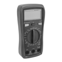
1. Plug black test lead into COM Jack.
Plug red test lead into VΩmA Jack.
2. Turn Rotary Dial to the
(continuity) position.
3. Connect the test leads across
the circuit to be measured.
4. Read measured resistance on the
Display. If measured resistance is less
than 30Ω Meter will beep; if the circuit
is open, the display will indicate “OL”.
5. When testing is complete, turn
Rotary Dial to OFF, remove
Test Leads and store with Meter.
Diode Measurement
Test voltage drop in diodes.
WARNING! TO PREVENT SERIOUS
INJURY: To prevent electric shock, turn off
all power and fully discharge capacitors on
the circuit under test before measuring.
1. Plug black test lead into COM Jack.
Plug red test lead into VΩmA Jack.
2. Turn Rotary Dial to the
(diode) position. Press the
HOLD/SELECT button so
is displayed on the screen.
3. Connect red probe to diode’s anode
and black probe to its cathode.
4. Read measured forward biased
voltage drop on the Display.
Note: If the leads are reversed, or the
diode has a voltage drop greater than the
meters limit of 2.1 volts, OL is displayed.
5. When testing is complete, turn
Rotary Dial to OFF, remove
Test Leads and store with Meter.