25
7. AIR CONDITIONER INSTALLATION
OUTDOOR UNIT LOCATION SELECTION
Select a location where the surface can support the weight and vibration of the
outdoor unit and where the noise and air flows generated by it would not be
amplified and disturb the users of the AC and their neighbors. There should be
a sufficient free space for the installation and subsequent maintenance of the
outdoor unit.
There should be enough free space in order not to restrict air circulation and
no obstructions at the air intake and discharge sides. The impact of strong
winds on the outdoor unit should be excluded. The impact of direct sunlight
and precipitation on the outdoor unit should be minimized. The installation of
protective hoods and screens is recommended in areas with abundant snowfalls.
The outdoor unit should be located at least 3 meters away from radio and TV
receivers in order to minimize the probability of sound and picture distortion
during operation. The outdoor unit should be installed perfectly level. The support
brackets of the outdoor unit should be securely fastened. Since liquid may flow
from the outdoor unit, no objects should be located near it which can be damaged
by moisture.
The following regulations should be observed during AC operation at low ambient
temperatures:
Do not install the outdoor init in locations where its air inlet and outlet openings
may be directly affected by winds. To avoid wind impact the outdoor unit should
be mounted with the intake side facing the wall, and the outlet opening should
be provided with a protective screen. The outdoor unit should be installed above
the snow cover level to avoid the ingress of snow into the unit.
INDOOR UNIT LOCATION SELECTION
Select a location where the surface can support the weight and vibration of
the indoor unit. There should be a sufficient free space for the installation and
subsequent maintenance of the indoor unit.
There should be enough free space in order not to restrict air circulation and no
obstructions on the air discharge side. The indoor unit should be located at least
1 meter away from radio or TV receivers in order to minimize the probability
of sound and picture distortion during operation. The impact of direct sunlight
and other heat sources should be minimized. The indoor unit should be installed
perfectly level. The mounting bracket of the indoor unit should be securely
fastened.
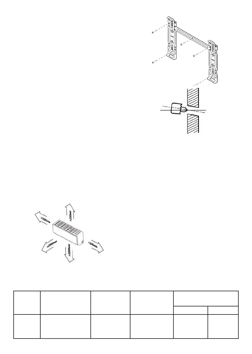
INDOOR UNIT MOUNTING DIMENSIONS
MAKING THE HOLE IN THE WALL
Select the location for the wall hole.
Before drilling the hole make sure that there are no embedded electrical cables
or pipelines inside the wall.
Drill a hole, 60 to 80 mm in diameter, at a slight angle towards the outdoor unit.
Insert a liner if necessary.
CONNECTING INTER
-
UNIT ELECTRIC CABLE AND POWER SUPPLY CABLE
Refrigerant Tube Flaring
Properly cut the copper tube of the required length with a tube cutter. Remove
all burrs from the cut edge of the tube. When deburring the cut hold the tube
with the cut end facing down to prevent metal shavings from getting inside the
tube. Put a tapered ring nut of the proper size on the tube. Be careful as you will
not be able to install the ring nut after flaring the tube end. Flare the tube end
using a specialized tool and observing all required procedures relevant for this
type of work. Check the resulting flare, it should have the same length and a
smooth edge around the whole circumference and a shiny inner surface without
scratches. If the flare is defective, cut the flared end away and repeat the flaring
process.
Refrigerant Tube Connection
Align the pipelines and tighten the tapered ring nut by hand to a stop.
Hold the nozzle from rotating with a spanner and tighten the ring nut with a
torque wrench, observing the torque specified in the table.
Table 1. REFRIGERANT PIPES, LENGTH AND HEIGHT LIMITATIONS
Min. Tube
length
(m)
Maximum allowable tube length
without additional refrigerant
charge
(m)
Maximum allowable
tube length
Maximum allowable
mounting height difference
between the indoor and
outdoor units
Quantity of additional refrigerant
(g/m)
< 12000 BTU/h > 18000 BTU/h
2 5
models:
7/12 - 25 m,
18/24 - 30 m
models:
7/12 - 12 m,
18/24 - 18 m
20 30