33
2. Outdoor unit
Remove the electrical panel cover.
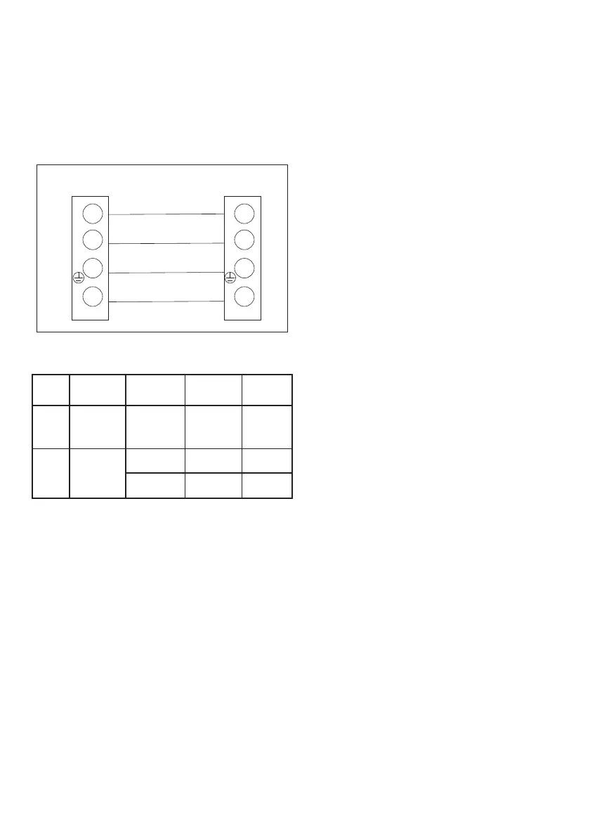
Connect the connecting wires in accordance with the connection
diagram on page 17 and in Fig. 14.
Reinstall the electrical panel cover plate.
Note:
– Ensure that all wires are securely fastened, do not come loose or
disconnect.
– The provided diagrams are common for all models and can vary
slightly for your specific model.
Brown
Indoor unit Outdoor unit
Blue
Black
Yellow-green
1 1
2 2
3 3
4 4
Figure 14
Table 3
Model Connecting
power cable
Signal cable Power
cable
≤
18000
BTU/h
Max length 10 m 10 m 5 m
≤
36000
BTU/h
Cross-
section
≥ 2,5 mm
2
≥ 1,5 mm
2
≥ 1,5 mm
2
≥ 2,5 mm
2
≥ 1,5 mm
2
≥ 2,5 mm
2
TABLE OF FAULT CODES ON PAGE 37!