Page 8 For technical questions, please call 1-888-866-5797. Item 62913
SAFETY OPERATION MAINTENANCEINSTALLATION
Mounting to a Truck Bed
1. Before mounting, if needed, reinforce the area with plywood or steel plating.
2. With assistance, move the compressor to the truck bed location and mark the floor of the truck
bed through the holes in the compressor’s feet. Check for any hidden wiring or cables and
adjust the location for the holes as needed. Then, temporarily set the compressor aside.
3. Drill the four 1/2″ diameter holes through the truck bed and any reinforcing materials.
4. Set the compressor back in place, and align the foot holes with the pre-drilled holes. Use four 1/2″
diameter, bolts, washers and lock washers (all not included) to secure the compressor in place.
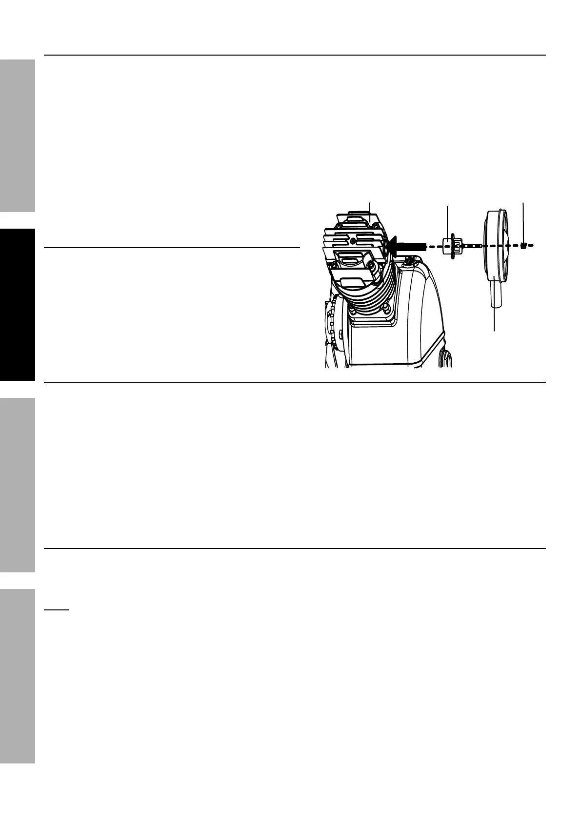
Assembly
To install the Muffler Assembly (8), fit the Connector into
the Muffler Assembly and slide the assembly into the
hole on the side of the First Stage Cylinder Head (5).
Secure in place with the Wing Nut.
Breaking in the Compressor
1. Turn the Engine off.
Insert a male coupler (sold separately) into the female Quick Coupler and fully open all regulators and valves.
2. Check all fluid levels in the engine and pump.
3. Start the engine following the General Operating Instructions.
4. Let the unit run for 30 minutes. Air will expel freely through the Coupler.
5. Turn the Engine OFF.
6. Remove the male coupler.
Air Connection Setup
1. Connect a regulator valve, an inline shut off valve and a 1/4″ NPT air hose to the
Quick Coupler (all sold separately). The air hose must be long enough to reach the
work area with enough extra length to allow free movement while working.
Note: An in-line shutoff ball valve is an important safety device because it controls the air supply even
if the air hose is ruptured. The shutoff valve should be a ball valve because it can be closed quickly.
2. Depending on the tool that will be used with this compressor, incorporate additional components, such as
an in-line oiler, a filter, or a dryer (all sold separately), as shown on Figure A on page 9. Consult air
tool’s manual for needed accessories. See Typical Air Line Setup charts on the following pages.
This is a truckbed compressor, so use the portable setup as a model.
Muffler
Assembly (8)
Wing Nut
Connector
First Stage
Cylinder Head (5)