EasyManua.ls Logo

Central Pneumatic 93458 User Manual

Central Pneumatic 93458
16 pages
To Next Page IconTo Next Page
Page #1 background imageLoading...
Page #1 background image
Visit our website at: http://www.harborfreight.com
Email our technical support at: productsupport@harborfreight.com
Owners Manual & Safety Instructions
Save This Manual Keep this manual for the safety warnings and precautions, assembly,
operating, inspection, maintenance and cleaning procedures. Write the product’s serial number in the
back of the manual near the assembly diagram (or month and year of purchase if product has no number).
Keep this manual and the receipt in a safe and dry place for future reference. 18e
When unpacking, make sure that the product is intact
and undamaged. If any parts are missing or broken,
please call 1-888-866-5797 as soon as possible.
Copyright
©
2005 by Harbor Freight Tools
®
. All rights reserved.
No portion of this manual or any artwork contained herein may be reproduced in
any shape or form without the express written consent of Harbor Freight Tools.
Diagrams within this manual may not be drawn proportionally. Due to continuing
improvements, actual product may differ slightly from the product described herein.
Tools required for assembly and service may not be included.
Read this material before using this product.
Failure to do so can result in serious injury.
SAVE THIS MANUAL.
Question and Answer IconNeed help?

Do you have a question about the Central Pneumatic 93458 and is the answer not in the manual?

Central Pneumatic 93458 Specifications

General IconGeneral
Operating Pressure90 PSI
Rivet Size3/32 in., 1/8 in., 5/32 in., 3/16 in.
Air Inlet Size1/4 in. NPT
Average Air Consumption4 CFM
TypePneumatic Rivet Tool
CapacityRivets up to 3/16 in.

Summary

Warning Symbols and Definitions

Hazard Level Definitions

Defines DANGER, WARNING, CAUTION, and NOTICE levels for hazardous situations.

Important Safety Instructions

General and Work Area Safety

Read all instructions, keep area clean/lit, avoid explosive atmospheres, keep bystanders away.

Personal Safety Precautions

Operator Readiness and Attire

Stay alert, dress properly, avoid distractions, use safety equipment.

Tool Use and Care Guidelines

Workpiece Securing and Tool Operation

Secure workpiece, use correct tool, ensure switch function, disconnect air for adjustments.

Storage and Maintenance Best Practices

Store tool safely, maintain with care, check for damage, use intended accessories.

Air Source Requirements

Air Source Specifications and Warnings

Use clean, regulated air up to 200 psi; never use flammable/bottled gases.

Symbols and Specific Safety Instructions

Technical Symbol Definitions

Defines abbreviations like PSI, BPM, CFM, SCFM, NPT, NPS.

Safety Symbol Meanings

Explains warnings for eye, hearing, respiratory injury, and explosion risks.

Specific Safety Instructions

Pre-Use Checks and Handling

Attach Safety Cap, understand manual limits, obey compressor manual, install shutoff valve, handle tool carefully.

Vibration Precautions

Health Risks and Reduction

Consult doctor if symptoms arise; reduce exposure by using low vibration tools, taking breaks, gripping lightly.

Functional Description and Specifications

Tool Specifications

Lists Maximum Air Pressure, Air Inlet, Air Consumption, Rivet Pin Capacity, Maximum Pull Force.

Components and Controls

Key Component Identification

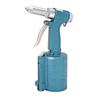
Identifies Head, Nosepiece, Trigger, Quick Connector, Pin Cap and other parts.

Initial Tool Set Up

Air Supply Connection and Adjustment

Connect filter, regulator, shutoff valve; adjust pressure, check connections.

Air Supply Safety Warnings

Prevent explosion from wrong gases and accidental operation via proper disconnection.

Post-Use Air Supply Disconnection

Turn off, detach air supply, discharge pressure, and release trigger to prevent accidental operation.

Operating Instructions

Pre-Operation Inspection and Priming

Inspect tool for damage, prime cylinder with hydraulic fluid, and install nosepiece.

Workpiece and Work Area Setup

Work Area Preparation

Designate clean, well-lit area, route air hose safely, secure workpieces, check for hazards.

General Operating Instructions

Tool and Rivet Preparation

Secure pin cap, attach nosepiece, attach air hose, set pressure.

Rivet Installation and Operation

Insert rivet, hold tool firmly, squeeze trigger to activate, check rivet security.

Addressing Insufficient Force and Post-Use

Troubleshoot force issues, turn off tool, detach air, clean, and store.

User-Maintenance Instructions

Pre-Use Inspection and Air Supply Maintenance

Inspect tool condition, maintain air supply daily, drain moisture filter.

Jaw Cleaning and Replacement

Jaw Disassembly, Cleaning, and Reassembly

Remove, clean, lubricate jaws; reassemble jaw cases and check tightness.

Troubleshooting Guide

Common Problems and Solutions

Addresses jaw slipping, short stroke, weak pull, leaks, loose rivets, deformed heads.

Service Safety Precautions

Follow safety precautions when diagnosing or servicing; disconnect air supply before service.

Parts List and Diagram Information

Parts Identification and Recording

Lists parts with numbers, describes how to record serial number or purchase date.

Assembly Diagram

Main Tool and Air Cylinder Assembly

Diagrams showing assembly of the riveter's main body, head, and air cylinder components.

Accessory Components Diagram

Diagram showing assembly of smaller components like triggers, valves, and nosepieces.

Limited 90 Day Warranty

Warranty Terms and Claim Process

Details warranty coverage, exclusions, and the procedure for making a claim.