CLEAHMI21 EXTERNAL HMI – PRODUCT DATA
EN0Z-0988GE51 R1018
3
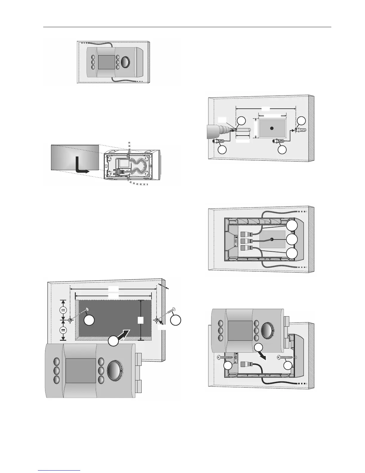
Fig. 8. Wall mounting example (magnet option)
Alternatively, a metal plate (incl. in delivery) can be attached
for handheld use (see section "Handheld Option" below).
Handheld Option
In the case of the handheld option, proceed as described in
Fig. 3 to Fig. 7). Finally, attach the metal plate (see Fig. 9),
which completely covers the rear of the device.
Fig. 9. Attaching metal plate
Screw-Mounting into Panel Door Cut-Out
In the case of screw-mounting into a panel door cut-out (door
thickness: 1…2.5 mm), proceed as follows (see also Fig. 10):
1. Prepare a suitably dimensioned (157 X 58 mm) cut-out
with bore-holes (Ø 5 mm) at a distance of 166 mm
apart and slide the CLEAHMI21 into place.
2. Insert and fasten the two M4x6 (DIN 7985A) screws
(incl. in delivery).
3. Finally, plug the connection cable into the RJ45 socket
and loop it through the cable guide and cable outlet
(see Fig. 7).
166
157
58
2 2
1
Ø 5
1
.
.
.
2
.
5
Fig. 10. Panel door mounting (in mm)
Wall-Mounting (Screw Option)
In the case of wall-mounting with screws, proceed as follows
(see also Fig. 11 and Fig. 13):
1. Place two suitably dimensioned bore-holes (Ø 6 mm,
with a min. depth of 35 mm) at a distance of 164 mm
apart. Installation over a standard flush-mounted box
(max. 140 X 35 mm) is optional.
2. Insert the two dowels (incl. in delivery) until snug.
164
Ø 6
22
1 1
MAX. 140
MAX. 65
OPTIONAL
MIN. 35
Fig. 11. Wall-mounting (screw option), steps 1+2
3. Position the sub-base (with the connection cable
already in position through the upper [a'] or lower [a]
cable outlet or from the flush-mounted box [a'']) over
the two bore holes and insert and fasten using the two
screws (incl. in delivery).
a
a‘
a‘‘
Fig. 12. Positioning sub-base and cables
4. Finally, plug the connection cable into the RJ45
socket, loop it through the cable guide and cable outlet
(see Fig. 7), and then click the CLEAHMI21 into the
sub-base.
3 3
4
Fig. 13. Wall-mounting (screw option), steps 3+4
 Loading...