J
John GrossJul 31, 2025
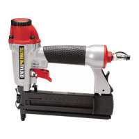
Why is my CentralPneumatic 68020 Nail Gun not driving nails deep enough?
- SSteven RiceJul 31, 2025
If your CentralPneumatic Nail Gun isn't driving fasteners deep enough, first adjust the depth setting if your tool has one. Then, check your air supply to ensure proper pressure (PSI) at the tool's inlet, without exceeding the maximum. Also, ensure the tool is correctly lubricated with air tool oil and grease. Check for and clean any buildup on the air inlet screen, if equipped. Finally, a qualified technician may need to clean and lubricate the internal mechanism, and you might need to install an in-line filter.