Do you have a question about the Century B-VMH36SD-1 and is the answer not in the manual?
General safety instructions to prevent injury and property damage.
Key warnings and cautions for installation and operation, including environmental factors.
Lists model names for indoor and outdoor units with their capacities.
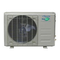
Diagram illustrating physical parts of indoor and outdoor units.
Table detailing width, depth, and height for various indoor unit models.
Table detailing dimensions for outdoor units, including service space requirements.
Specifies torque values for installation fasteners based on outside diameter.
Guidelines for selecting power cords based on appliance amperage and AWG wire size.
Table showing pipe sizes and maximum elevation/length for different models.
Step-by-step guide for initial installation, including leak testing and evacuation.
Procedure for adding refrigerant after the system has been running for many years.
Instructions for re-installing units after repair, for both indoor and outdoor components.
Defines abbreviations used for temperature sensors and other parameters.
Explains icons and indicators on the indoor display board.
Lists various protection mechanisms for the compressor, fan, and inverter module.
Describes different operating modes like Fan, Cooling, Heating, Drying, and Auto.
Instructions on how to access and use the point check function via the remote controller.
Table listing error codes, their meanings, and related display statuses.
Explains LED indicators and error codes for the outdoor unit.
Provides diagnosis and solutions for various error codes, starting with EEPROM issues.
Troubleshooting steps for indoor/outdoor unit communication errors (E1) due to wiring or PCB faults.
Diagnosis and solution for zero crossing detection errors (E2), focusing on connections and PCB.
Troubleshooting steps for indoor fan speed control errors (E3/F5), checking wiring, motor, and PCB.
Diagnosing and resolving temperature sensor issues like open circuits or short circuits.
Procedure for diagnosing and resolving refrigerant leakage issues detected by the unit.
Troubleshooting steps for overload current protection (F0), checking power supply, blockages, and components.
Diagnosing and resolving IPM or IGBT over-current protection faults (P0) related to wiring or components.
Troubleshooting steps for over/under voltage protection (P1), checking power supply, connections, and reactor.
Steps to diagnose and resolve IPM high temperature protection faults (P2), checking mounting and PCB.
Troubleshooting for inverter compressor drive errors (P4), covering wiring, IPM, fan, and compressor checks.
Procedure for diagnosing and resolving low pressure protection issues (P6), checking wiring, protector, and refrigerant.
Method to check temperature sensors (T1-T4, TP) by measuring resistance with a tester.
Table providing resistance values for temperature sensors at various Celsius temperatures.
Table showing resistance values for the TP sensor at different Celsius temperatures.
Steps to measure IPM resistance between specific terminals using a digital tester.
Procedure to measure winding resistance values for indoor AC fan motors.
Tables and charts showing pressure readings for heating operation at various temperatures.
Step-by-step guide with images for removing the indoor unit's front panel.
Instructions for removing electrical components from the indoor unit.
Steps to remove the evaporator assembly from the indoor unit.
Procedure for removing the fan and motor from the indoor unit.
Steps to remove the panel plate from outdoor units A-VMH09SU-1 and A-VMH12SU-1.
Instructions for removing the fan assembly from the outdoor unit.
Steps to remove electrical components from the outdoor unit.
Procedure for removing the four-way valve assembly.
Steps to remove the compressor from the outdoor unit.
Steps to remove the panel plate from outdoor unit A-VMH18SU-1.
Instructions for removing the fan assembly from the 18K outdoor unit.
Steps to remove electrical components from the 18K outdoor unit.
Steps to remove the panel plate from outdoor units A-VMH30SD-1 and A-VMH36SD-1.
Instructions for removing the fan assembly from 30K/36K outdoor units.
Steps to remove electrical components from 30K/36K outdoor units.
Procedure for removing the four-way valve assembly.
Steps to remove the compressor from the outdoor unit.
| Brand | Century |
|---|---|
| Model | B-VMH36SD-1 |
| Category | Air Conditioner |
| Language | English |