EasyManua.ls Logo

Cessna 150 Series - INDUCTION AIR SYSTEM; DESCRIPTION; REMOVAL AND INSTALLATION; IGNITION SYSTEM

Cessna 150 Series
284 pages
Print Icon
To Next Page IconTo Next Page
To Previous Page IconTo Previous Page
Loading...
NOTE
b.
Remove
intake
pipes
by
disconnecting
hose
and
removing
nuts
and
washers
attaching
pipes
to
cyl-
After
each
adjustment
to
the
idle
mixture,
inders.
run
engine
up
to
approximately
2000
RPM
c.
Installation
of
the
system
is
the
reverse
of
the
to
clear
engine
of.excess
fuel
to
obtain
a
preceding
steps.
Use
new
gaskets
at
installation.
correct
idle
speed.
11-46.
IGNITION
SYSTEM.
11-43.
INDUCTION
AIR
SYSTEM.
11-47.
DESCRIPTION.
Sealed,
lightweight
Slick
11-44.
DESCRIPTION.
Ram
air
to
the engine
enters
magnetos
are
used
on
the
engine.
Both
magnetos
the
induction
airbox through
an
opening
in
the
forward
are
equipped with
impulse
couplings.
The
magnetos
part
of
the
lower
engine
cowling
nose
cap. The
air
is
MUST
NOT
BE DISASSEMBLED.
Internal
timing
is
filtered
through
a
filter
which
is
located at
the
open-
fixed
and
the
breaker
points
are
not
adjustable.
Tim-
ing
in
the
nose cap.
From
the
induction
airbox
the
ing
marks
are
provided
on
the
distributor
gear
and
filtered
air
is
directed
to
the
inlet
of
the
carburetor,
distributor
block,
visible
through
the
air
vent
holes,
mounted
on
the
lower
side
of
the
engine,
and
through
for
timing
to
the
engine.
A
timing
hole
is
provided
the
carburetor,
where
fuel
is
mixed
with
the
air,
to in
the
bottom
of
the
magneto
adjacent
to
the
magneto
the
intake
manifold.
From
the
intake
manifold, the
flange.
A
timing
pin
(or
0.093
inch
6-penny
nail)
can
fuel-air
mixture
is
distributed
to
each
cylinder
by
be
inserted
through
this
timing
hole
into the mating
separate
intake
pipes.
The
intake
pipes
are
attached
hole
in
the
magneto
rotor
shaft
to
lock
the
magneto
to
the intake
manifold
with
hose
and
clamps
and
to the
approximately
in
the
proper firing
position.
Slick
cylinder
with
a
two
bolt
flange
which
is
sealed
with
a lightweight
ignition
harness
is
used
with
the
light-
gasket.
The
induction
airbox
contains
a
valve,
oper-
weight
magnetos.
For
ignition
harness
repair
refer
ated
by
the
carburetor
heat
control
in
the
cabin,
which
to
the
manufacturer's
Service
Manual
permits
air
from
an
exhaust
heated
source
to
be
se-
lected
in
the
event
carburetor
icing
or
filter
icing
WARNING
should
be
encountered.
During
all
magneto
maintenance,
always
11-45.
REMOVAL
AND
INSTALLATION.
take
proper precautions
to
make
sure
the
a.
Remove
airbox
and
carburetor
as
outlined
in
engine
can
not
fire
or
start
when
the
pro-
paragraph
11-41.
peller
is
moved.
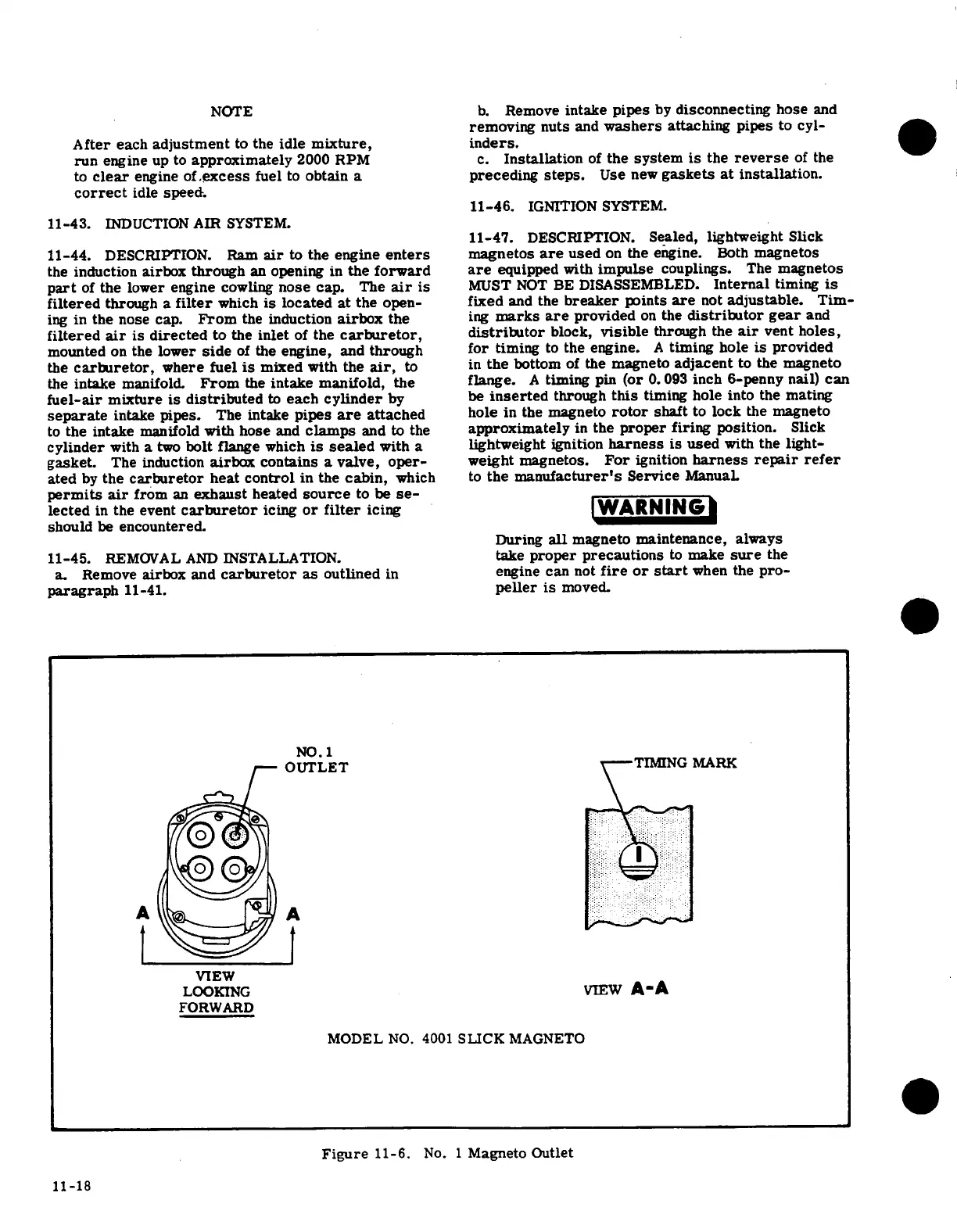
NO.1
OUTLET
TIMING
MARK
VIEW
LOOKING
VIEW
A-A
FORWARD
MODEL
NO.
4001
SLICK
MAGNETO
Figure
11-6.
No.
1
Magneto
Outlet
11-18

Table of Contents