REVISED
FUELQUANTITY
DATA
LMOD182
Fuses
and
Circuit
Breakers,
2-6
crosswind,
2-17
1973 AIRCRAFT
(SERIAL 18262251 AND ON)
distance table
6-9
1974 AIRCRAFT
(ALL
SERIALS)
'
SKYLANE
1975 AIRCRAFT
(ALL SERIALS)
forced,
3-1
G
normai,
1-7,
2-17
precautionary
with power,
3-2
Graph, Loading,
4-7
short
field,
2-17
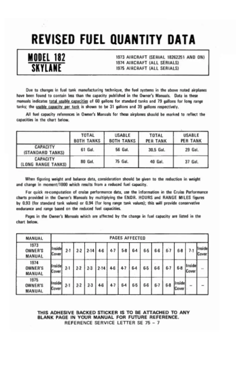
Due
to changes in fuel
tank
manufacturing
technique, the fuel
systems in the above noted airplanes Gross
Weight,
inside front cover
Landing Gear
Servicing,
inside
have been found
to
contain less than the
capacity
published in the
Owner's
Manuals. Data in these
Ground
Handling,
5-1
back cover
manuals indicates
total
usable capacities
of
60
gallons for standard tanks
and
79
gallons
for
long
range
Ground Service Plug Receptacle,
main/nose
wheel tire
pressure,
tanks;
the usable
capacity per
tank
is shown
to
be 31 gallons and
39 gallons respectivelY·
7-1
inside
back
cover
All fuel
capacity references
in
Owner's
Manuals for these
airplanes should be marked to reflect the
nose
gear shock
strut
servicing,
capacities in the
chart
below.
inside back
cover
H
Let-Down,
1-6
Lighting Equipment,
2-6
TOTAL
USABLE
TOTAL
USABLE
Handling,
Ground,
5-1
exterior
lighting,
2-6
BOTH
TANKS BOTH
TANKS PER TANK PER TANK
CAPACITY
Harnesses,
Shoulder,
2-9,
2-10
interior
lighting,
2-7
(STANDARD
TANKS)
61 Gal. 56 Gal.
30.5
Gal.
29
Gal.
Headset-Microphone,
7-5
Limitations, Airspeed,
4-2
CAPACITY
Heating,
Ventilating
and Defrosting Limitations, Engine
Operation,
(LONG
RANGE
TANKS)
80
Gal.
75
Gal.
40
Gal.
37 Gal.
System,
Cabin,
2-8
4-2
Hot Weather
Operation,
2-21
Loading Arrangements
Diagram,
4-5
Loading
Graph,
4-7
When
figuring
weight
and
balance
data,
consideration
should
be
given
to
the
reduction in weight Loading Problem,
Sample,
4-6
and
change in moment/1000
which
results
from
a
reduced fuel
capacity.
Long
Range Fuel
Tanks,
2-3
For quick
re-computation
of
cruise
performance
data,
use the
information in
the Cruise
Performance
Low Oil
Pressure,
3-8
charts
provided
in
the Owner's
Manuals by
multiplying the ENOR. HOURS
and
RANGE
MILES
figures
Indicator,
Fuel Quantity,
4-3
by 0.93 (for
standard tank
values) or
0.94 (for
long
range tank
values); this
will
provide
conservative
Indicator,
True Airspeed,
7-10
endurance and
range based
on
the
reduced
fuel
capacities.
Inspection Requirements,
5-6
M
Pages
in the Owner'sManuals
which are affected by
the change in fuel
capacity
are listed
in the
Instrument
Markings,
Engine,
chart below.
4-2
MAA
Plate/Finish
Trim
Plate,
5-4
Instrument Panel Diagram,
1-8
Magneto
Malfunction,
3-8
Insufficient Rate of
Electrical
Maneuvers
-
Normal Category,
4-1
MANUAL
PAGES
AFFECTED
Charge,
3-9
Manifold
Pressure Gage,
4-3
1973
Integrated
Seat
Belt/Shoulder
Har-
Markings,
Airspeed
Indicator,
4-2
OWNER'S
Inside
2-1
2-2 2-14
4-6
4-7
5-8
64
6-5
6-6
6-7
6-8
7-1
Inside
nesses With Inertia Reels,
2-10
Markings,
Engine
Instrument,
4-2
MANUAL
Cover
Cover
Interior
Care,
5-4
Master
Switch,
2-3
Interior
Lighting,
2-7
Maximum
Glide Diagram,
6-10
OWNER'S
Inside
2-1
22
2-3
2-14
4-6
4-7 6-4 6-5 6-6
6-7 6-8
Inside
_
Maximum Performance
Climb,
1-6
MANUAL
Cover
Cover
Maximum
Performance
Take-Off,
1975
L
1-5
OWNER'S
Inside
2-1
22
2-3
4-6
47
6-4 6-5 6-6
6-7
6-8
Inside
- -
Maximum
Rate-Of-Climb
Data
MANUAL
Cover
Cover
Landing,
2-17
Chart,
6-3
after,
1-7
Microphone-Headset, 7-5
balked,
1-6,
2-17
Moment
Envelope,
Center of
THIS
ADHESIVE BACKED
STICKER
IS TO BE
ATTACHED TO ANY
before,
1-6
Gravity,
4-8
BLANK PAGE IN YOUR
MANUAL
FOR
FUTURE
REFERENCE.
REFERENCE
SERVICE
LETTER SE 75
-
7
Index-3
REVISED
FUELQUANTITY
DATA
LMOD182
Fuses
and
Circuit
Breakers,
2-6
crosswind,
2-17
1973 AIRCRAFT
(SERIAL 18262251 AND ON)
distance table
6-9
1974 AIRCRAFT
(ALL
SERIALS)
'
SKYLANE
1975 AIRCRAFT
(ALL SERIALS)
forced,
3-1
G
normai,
1-7,
2-17
precautionary
with power,
3-2
Graph, Loading,
4-7
short
field,
2-17
Due
to changes in fuel
tank
manufacturing
technique, the fuel
systems in the above noted airplanes Gross
Weight,
inside front cover
Landing Gear
Servicing,
inside
have been found
to
contain less than the
capacity
published in the
Owner's
Manuals. Data in these
Ground
Handling,
5-1
back cover
manuals indicates
total
usable capacities
of
60
gallons for standard tanks
and
79
gallons
for
long
range
Ground Service Plug Receptacle,
main/nose
wheel tire
pressure,
tanks;
the usable
capacity per
tank
is shown
to
be 31 gallons and
39 gallons respectivelY·
7-1
inside
back
cover
All fuel
capacity references
in
Owner's
Manuals for these
airplanes should be marked to reflect the
nose
gear shock
strut
servicing,
capacities in the
chart
below.
inside back
cover
H
Let-Down,
1-6
Lighting Equipment,
2-6
TOTAL
USABLE
TOTAL
USABLE
Handling,
Ground,
5-1
exterior
lighting,
2-6
BOTH
TANKS BOTH
TANKS PER TANK PER TANK
CAPACITY
Harnesses,
Shoulder,
2-9,
2-10
interior
lighting,
2-7
(STANDARD
TANKS)
61 Gal. 56 Gal.
30.5
Gal.
29
Gal.
Headset-Microphone,
7-5
Limitations, Airspeed,
4-2
CAPACITY
Heating,
Ventilating
and Defrosting Limitations, Engine
Operation,
(LONG
RANGE
TANKS)
80
Gal.
75
Gal.
40
Gal.
37 Gal.
System,
Cabin,
2-8
4-2
Hot Weather
Operation,
2-21
Loading Arrangements
Diagram,
4-5
Loading
Graph,
4-7
When
figuring
weight
and
balance
data,
consideration
should
be
given
to
the
reduction in weight Loading Problem,
Sample,
4-6
and
change in moment/1000
which
results
from
a
reduced fuel
capacity.
Long
Range Fuel
Tanks,
2-3
For quick
re-computation
of
cruise
performance
data,
use the
information in
the Cruise
Performance
Low Oil
Pressure,
3-8
charts
provided
in
the Owner's
Manuals by
multiplying the ENOR. HOURS
and
RANGE
MILES
figures
Indicator,
Fuel Quantity,
4-3
by 0.93 (for
standard tank
values) or
0.94 (for
long
range tank
values); this
will
provide
conservative
Indicator,
True Airspeed,
7-10
endurance and
range based
on
the
reduced
fuel
capacities.
Inspection Requirements,
5-6
M
Pages
in the Owner'sManuals
which are affected by
the change in fuel
capacity
are listed
in the
Instrument
Markings,
Engine,
chart below.
4-2
MAA
Plate/Finish
Trim
Plate,
5-4
Instrument Panel Diagram,
1-8
Magneto
Malfunction,
3-8
Insufficient Rate of
Electrical
Maneuvers
-
Normal Category,
4-1
MANUAL
PAGES
AFFECTED
Charge,
3-9
Manifold
Pressure Gage,
4-3
1973
Integrated
Seat
Belt/Shoulder
Har-
Markings,
Airspeed
Indicator,
4-2
OWNER'S
Inside
2-1
2-2 2-14
4-6
4-7
5-8
64
6-5
6-6
6-7
6-8
7-1
Inside
nesses With Inertia Reels,
2-10
Markings,
Engine
Instrument,
4-2
MANUAL
Cover
Cover
Interior
Care,
5-4
Master
Switch,
2-3
Interior
Lighting,
2-7
Maximum
Glide Diagram,
6-10
OWNER'S
Inside
2-1
22
2-3
2-14
4-6
4-7 6-4 6-5 6-6
6-7 6-8
Inside
_
Maximum Performance
Climb,
1-6
MANUAL
Cover
Cover
Maximum
Performance
Take-Off,
1975
L
1-5
OWNER'S
Inside
2-1
22
2-3
4-6
47
6-4 6-5 6-6
6-7
6-8
Inside
- -
Maximum
Rate-Of-Climb
Data
MANUAL
Cover
Cover
Landing,
2-17
Chart,
6-3
after,
1-7
Microphone-Headset, 7-5
balked,
1-6,
2-17
Moment
Envelope,
Center of
THIS
ADHESIVE BACKED
STICKER
IS TO BE
ATTACHED TO ANY
before,
1-6
Gravity,
4-8
BLANK PAGE IN YOUR
MANUAL
FOR
FUTURE
REFERENCE.
REFERENCE
SERVICE
LETTER SE 75
-
7
Index-3