Do you have a question about the Cessna 525C and is the answer not in the manual?
Detailed steps for removing the instrument panel from the aircraft.
Detailed steps for removing the instrument panel from the aircraft.
Detailed steps for installing the instrument panel onto the aircraft frame.
Specific issues for the GH-3900 system.
Steps to resolve the DCM Read Error message in the system.
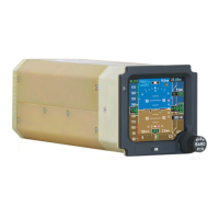
Detailed steps for removing the standby flight display.
Detailed steps for removing the standby flight display.
Detailed steps for installing the standby flight display.
Detailed steps for removing the configuration module.
Detailed steps for removing the configuration module.
Detailed steps for installing the configuration module.
Lists tools and consumables for DCM data loading.
Step-by-step instructions for loading DCM data onto the GH-3900.
Steps to verify the loaded DCM configuration files.
Step-by-step instructions for restoring DCM data.
Key operational check.
Steps to check the standby flight display function.
Verifying HDG annunciations after alignment calculations.
Verifying standby flight display heading during calibration check.