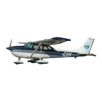
CESSNA
MODEL
172S NAV Ill
GFC 700 AFCS
SECTION 7
AIRPLANE AND SYSTEM DESCRIPTION
ELECTRICAL SYSTEM (Continued)
G1000 ANNUNCIATOR PANEL
All system alerts, cautions and warnings are shown on the right side of
the PFD screen adjacent
to
the vertical speed indicator. The following
annunciations are supported:
OIL
PRESSURE
LOW
FUEL L
LOW
VOLTS
STBY BATT
LOW VACUUM
LOW
FUEL R
HIGH VOLTS
CO LVL HIGH
Refer to the Garmin
G1
000 CRG Appendix A for more information
on
system annunciations.
MASTER SWITCH
The MASTER switch
is
a two-pole, rocker-type switch. The BAT side of
the switch
controls the main battery electrical power to the airplane.
The
ALT
side of the switch controls the alternator system.
In
normal operation, both sides of the switch (ALT and BAT) are
ON
simultaneously; however, the
BAT
side of the switch may
be
selected
separately
as
necessary. The AL T side of the switch can not
be
set
to
ON
without the BAT side
of
the switch also being set to ON.
If
the alternator system fails, the MASTER switch may be set
in
the
OFF position to preserve main battery capacity for later
in
the flight.
With the MASTER switch OFF and the STBY BATT switch
in
the
ARM
position, the standby battery will power the essential bus for a limited
time. Time remaining may
be
estimated by monitoring essential
bus
voltage. At 20 Volts, the standby battery has little or
no
capacity
remaining.
(Continued Next Page)
172SPHBUS-OO
u.s.
7-51
 Loading...