12
FinalSteps
A1 Reference and Ground
earclip must be applied for
impedance check to operate.
10.OptimizeSensorContact
After properly positioning the headset on the subject,
obtain direct contact on all sensors before recording.
The Quick-32r has impedance-level LEDs on the top
of each sensor pod. The LEDs live-check the system’s
impedance and have a threshold of 2,500 kΩ.
Use the LEDs to assist in making contact with the scalp on
each position. Then bring up the impedance check in the
CGX Data Acquisition software under the Channels tab.
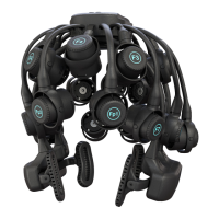
The impedance check presents a color-coded map of the
sensors on the device, corresponding to contact level:
Red Impedance out of range
(>2,500 kΩ default)
Green Impedance within range
(<2,500 kΩ default)
The range of impedances with dry sensors may be higher
than what you are accustomed to when working with
conventional wet sensor ampliers. CGX devices utilize
a combination of advanced electronics, shielding, and
mechanics to obtain EEG signals even when contact is
poor, and can tolerate sensor impedance up to 2,500 kΩ.
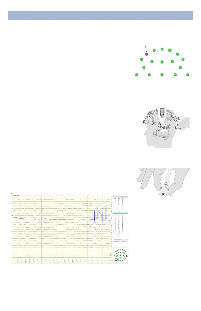
11.AdjustPods,IfRequired,ToImprove
ImpedanceMeasurements
Check for acceptable impedance measurements on each
channel.
To ensure good impedance measurements:
Grasp pod on sides to
reposition
Gently twist
swivel mechanism without
displacing pod
ImpedanceMap
Under The Channels Tab
Unacceptable
ThresholdSpikes
You may see a brief glitch in the EEG signal when electrode
impedance nears 2,500 kΩ. This is a natural eect when
the LED on the pod changes colors. Continue adjusting the
electrode until the impedance is below the threshold and
the artifact will disappear.
 Loading...