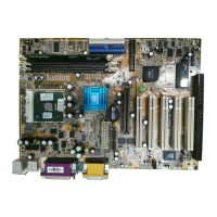
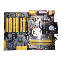
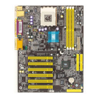
Chapter 2
8
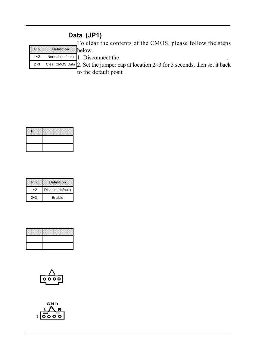
Pin Definition
1~2 Normal (default)
2~3 Clear CMOS Data
Pin Definition
1~2 Disable (default)
2~3 Enable
Pin Definition
1~2 Disable (default)
2~3 Enable
Clear CMOS Data (JP1)
To clear the contents of the CMOS, please follow the steps
below.
1. Disconnect the system power supply from the power source.
2. Set the jumper cap at location 2~3 for 5 seconds, then set it back
to the default position.
3. Connect the system's power and then start the system.
4. Enter BIOS's CMOS Setup Utility and choose Load Setup
Defaults. Type Y and press enter.
5. Set the system configuration in the Standard CMOS Setup
menu.
Power On By Keyboard (JP5)
This board is able to be turned on by the PS/2 keyboard (hot
key). To use this function, select a hot key of your choice at
the PS2KB Wakeup option under Wake Up Events in the BIOS's
Power On Management screen. You must also set this jumper's
cap to pins 2-3 to use this function.
Power On By USB (JP6/JP21)
This board is able to be turned on by a USB keyboard hot key
or a USB mouse click. To use this function, select a hot key of
your choice at the USB Resume From S3 option under Wake Up
Events in the BIOS's Power On Management screen. You must
also set this jumper's cap to pins 2-3 to use this function.
CPU Bus Frequency (JP20)
This jumper allows you to select the system bus frequency speed
of your CPU. Set the jumper cap to pins 1-2 for 100MHz FSB,
set the jumper cap to pins 2-3 for 133MHz FSB.
CD-ROM Audio-in (CN2)
Use the audio cable enclosed with your CD-ROM disk drive to
connect the CD-ROM to your mainboard. This will enable your
CD-ROM's audio function.
Auxiliary Audio-in (CN3)
This connector is for use with a secondary CD-ROM, DVD-ROM
or CDR/CDRW disk drive.
L
1
R
GND
Pin Definition
1~2 100MHz (default)
2~3 133MHz