5.0 Installation Guide
9
Please refer to the manual if any of these parts are damaged or missing.
1. Unpack the drill carefully. Locate parts listed above.
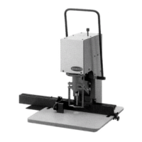
2. Lay drill head so the backside is on a flat surface (Figure 3). Place the sheet metal table
shim between the tabletop and the bottom of the drill base. Locate the four mounting bolts
and washers in the tool kit. Place the washers under the bolt heads and insert bolts through
the table into the drill base, finger tighten only.
Figure 3
3. Lift the drill so it is now standing upright, resting on the table support. Insert the two 5/16-
18x3/8 socket set screws found in the tool kit into the ends of the cross shaft. Place the two
ends of the handle into the holes in the cross shaft. With the bottom edges of the handle flush
with the bottom of the shaft, tighten the setscrews.
4. Next, install the backgauge. While holding the thumbscrew of the backgauge to the right side,
slide the backgauge onto the table. Lift the pressure foot up and slide the backgauge
underneath. Position the backgauge at the 1" marks on the table scales. Tighten the
thumbscrew.
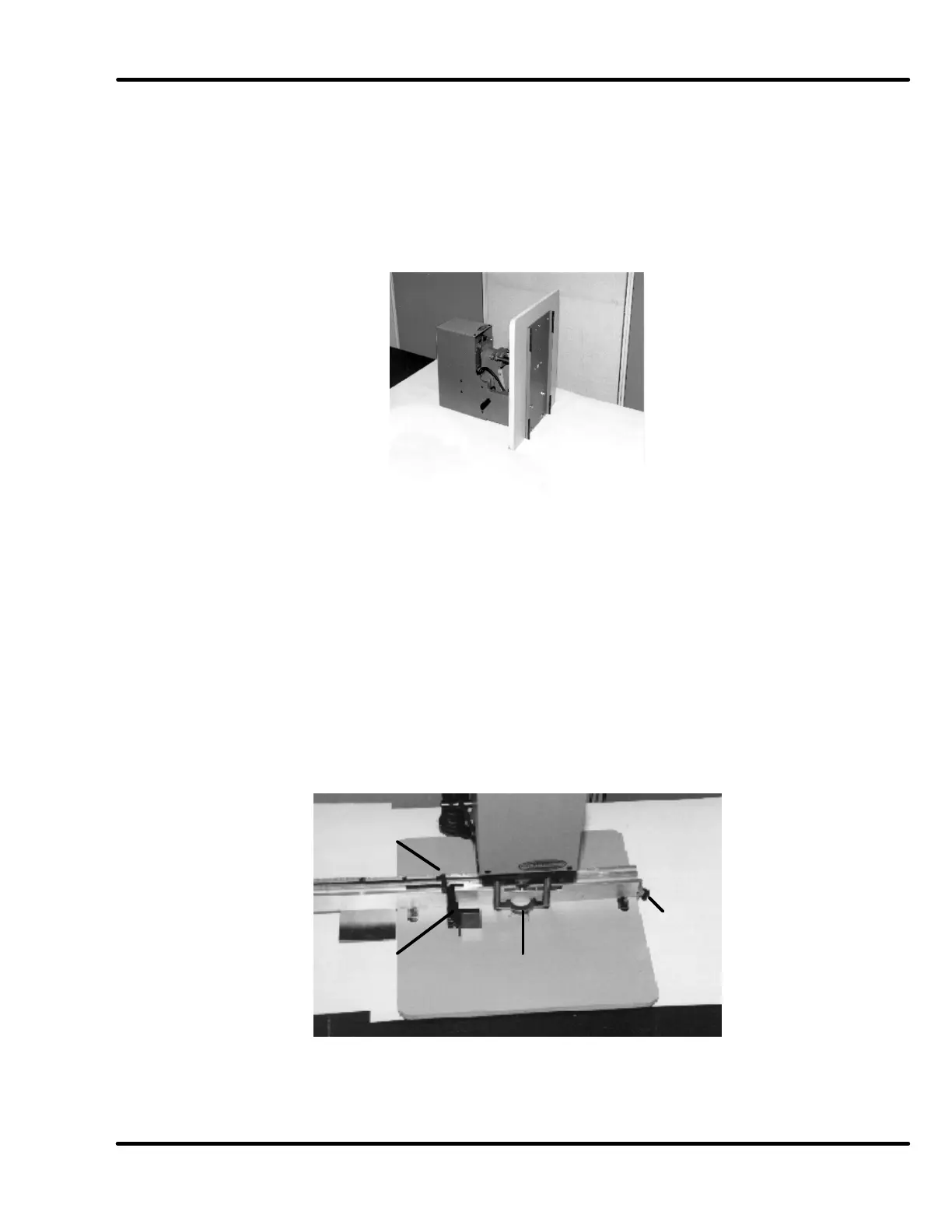
5. Position a side guide stop at the 3" mark on the backgauge. Align the side guide to this
position. Place the drift hole cover on the spindle; insert the hollow drill into the spindle and
the drill block into the table (Figure 4).
Figure 4
Position
stop at 3”
Align side
guide to stop
Insert drill and
drill block
Install
backgauge from
front with
thumbscrew on