EasyManua.ls Logo

Challenger AP11LCD - User Manual

Challenger AP11LCD
30 pages
Print Icon
To Next Page IconTo Next Page
Loading...
AP11LCD / AP11LED Manager Guide
AP11LED/LCD-Manager- Rev 02
1
Manager Guide
This User Guide tells you how to operate your intruder alarm system. To simplify this User
Guide we have assumed that the alarm system has been installed by a professional intruder alarm
system installer (the installer), and that the system is operating in a “typical” way. Aspects of
your system that are not “typical” will be described by your installer.
NOTE: If you have any questions about your intruder alarm system, then consult your installer,
see contact details at the front of this User Guide.
Indications on the system
Indications
LED steady on indication
LED flashing indication
LED off
Internal Sound
External Device: Strobe
External Siren: Bell
Using System
After you have finish system settings, you can use the system now. This section gives an
operation instructions how to set and unset the system as well as how to reset after an alarm.
Question and Answer IconNeed help?

Do you have a question about the Challenger AP11LCD and is the answer not in the manual?

Summary

Indications on the system

Using System

LED Keypad Operations

How to Set the System

Instructions for setting the intruder alarm system using the LED keypad.

How to OMIT a zone(s)

Guide on omitting specific zones from the alarm system when setting it.

Unsetting the System

Steps to disarm the intruder alarm system.

How to UNSET from Alarm and RESET

Procedure to disarm and reset the system after an alarm event.

LCD Keypad Operations

How to Set the System

Instructions for setting the intruder alarm system using the LCD keypad.

How to OMIT a zone(s)

Guide on omitting specific zones from the alarm system when setting it.

Unsetting the System

Steps to disarm the intruder alarm system using the LCD keypad.

How to UNSET from Alarm and RESET

Procedure to disarm and reset the system after an alarm event via LCD.

Event Log Messages

Zone Location and Programming

Errors and Omissions

Overview

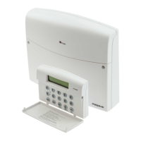
This document outlines the operation and programming of the Challenger AP11LCD / AP11LED Manager Guide, an intruder alarm system designed for professional installation. It serves as a user guide, detailing how to operate, set, unset, and maintain the system, including instructions for both LED and LCD keypads.

Function Description:

The Challenger intruder alarm system is designed to secure premises against unauthorized entry. It offers various setting modes, including "Full Set" for when the premises are vacated and "Part Set" for securing specific zones while allowing free movement in others (e.g., at night). The system incorporates a robust event logging feature, capable of storing up to 250 events, arranged by date and time, operating on a First In Last Out (FILO) principle. This log provides a comprehensive record of all system activities, including alarms, tamper events, and user operations.

The system supports multiple user codes, including a Manager's Code (default 0123) with full access to programming options, and up to 10 standard user codes (for LCD keypads, 2 for LED keypads). A "Holiday Code" can also be programmed, providing temporary access for others when the manager is absent, which becomes invalid once the manager uses the system again.

For enhanced security and maintenance, the system includes an "Engineer Program Mode" that requires authorization from the manager. This mode allows engineers to access advanced settings and perform system diagnostics. The "Test System" function offers three main parts: "Test Output" (for bell, strobe, and speaker), "Walk Test" (to check zone triggers and tampers), and "View Walk Test" (to review walk test results).

The system also features a "Chime Zone" function, which, when programmed, emits a special tone when a designated security zone is triggered in "DAY" mode, providing an audible alert without initiating a full alarm.

Important Technical Specifications:

While the document does not explicitly list detailed technical specifications like power consumption, battery type, or communication protocols, it implies several key features:

  • User Codes: Up to 10 user codes (4-digit, 0000-9999) for LCD keypads, 2 for LED keypads. A default Manager's Code (0123) is provided.
  • Event Log Capacity: Stores up to 250 events (FILO) for LCD keypads, 16 events for LED keypads.
  • Engineer Access: Authorized for a 3-hour window.
  • Output Tests: Includes tests for Bell, Strobe, and Speaker.
  • Tamper Detection: Detects various tamper events including Zone tamper, PA tamper, Fire tamper, Control Panel tamper, Bell Box tamper, Remote Keypad tamper, and EOLR Zone tamper.
  • Time and Date: Can be set in HH:MM and DD/MM/YY formats. Note: Time and Date will be lost if both main power and backup battery are cut.
  • Zone Omission: Allows temporary omission of faulty zones to enable system setting.
  • Panic Alarm: Activated by pressing '0' and '5' simultaneously on the keypad.

Usage Features:

  • Setting the System (Full Set/Part Set):
    • LED Keypad: In Day mode, enter user/manager code. Day LED flashes for 5 seconds. Press SET for Full arm, OMIT for Part 1, & for Part 2, or RESET to exit. Faults must be cleared before setting. Quick set is available by pressing SET.
    • LCD Keypad: In Day mode, enter 4-digit manager/user code. System displays "Welcome Manager" and "To Set Select [Full] [P1] [P2]". Select desired arm mode.
  • Unsetting the System:
    • LED Keypad: In Set mode, enter user/manager code. System returns to Day mode.
    • LCD Keypad: In Set mode, enter 4-digit manager/user code. System displays "Unset System Now" and then "Exit stopping by Manager", returning to Day mode.
  • Unsetting from Alarm and Resetting:
    • LED Keypad: In Set mode with an alarm event, enter user/manager code to stop the sound and view alarm events (first event flashing, others lit). Enter code again to return to Day mode.
    • LCD Keypad: In Set mode with an alarm event, enter manager/user code to stop the alarm and display the newest event. Enter code again to reset and return to Day mode.
  • Omit Zones:
    • LED Keypad: Set the system (Full/Part1/Part2). Press OMIT to enter omit zone window; all omit-allowed zones light up. Press the corresponding number key (1-9 for zones 1-9, 0 for zone 10) to toggle ON/OFF. Press PROG to accept, RESET to cancel.
    • LCD Keypad: In setting mode, press OMIT to enter omit zone window. Select a zone using OMIT or & keys.
  • Panic Alarm: Press 0 and 5 simultaneously on the keypad.
  • Manager Program Mode:
    • LED Keypad: In Day mode, press PROG 0123.
    • LCD Keypad: In Day mode, press PROG 0123.
  • Setup Codes (Change User Code):
    • LED Keypad: In Manager Menu, press 1 to select Setup User codes. Press 1 again to change User 1. Enter new 4-digit code. Press PROG to save, RESET to cancel.
    • LCD Keypad: In Manager Menu, press 1 to enter Setup Codes. Select the user (1-10) using number keys or OMIT/&. Press PROG to accept. Select "Change Code" and press PROG. Enter new 4-digit code. Press PROG to save.
  • Delete User Code:
    • LED Keypad: In Manager Menu, press 1 to select Setup User codes. Press 1 again to change User 1. Press OMIT to delete. Press RESET to return.
    • LCD Keypad: In Manager Menu, press 1 to enter Setup Codes. Select the user. Press PROG. Select "Delete Code" and press PROG.
  • View Event Log:
    • LED Keypad: In Manager Menu, press 2. Use 1 (oldest), 2 (older), 3 (newer), 4 (newest) to navigate. 9 clears all alarm events. Press RESET to exit.
    • LCD Keypad: In Manager Menu, press 2. Press PROG to view the most recent event. Use OMIT or & to view other events. Press PROG to view time and date.
  • Authorize Engineer Access:
    • LED Keypad: In Manager Program Mode, press 3. Engineer can access program mode within 3 hours. Press RESET to leave.
    • LCD Keypad: In Manager Program Mode, press 3. Press PROG to accept.
  • Set Chime Zone:
    • LED Keypad: In Manager mode, press &. Zone 3 LED ON indicates chime set. Use 1-0 keys to select/deselect zones. Press PROG to accept, RESET to cancel.
    • LCD Keypad: In Manager Menu, press 4 and PROG. Select zone (1-10) using number keys. Use OMIT or & to toggle ON/OFF. Press PROG to save.
  • Set Time (HH:MM):
    • LCD Keypad: In Manager Menu, press 6 and PROG. Enter new time (4 digits). Press PROG to save, RESET to cancel.
  • Set Date (DD/MM/YY):
    • LCD Keypad: In Manager Menu, press 7 and PROG. Select day of the week. Enter date (6 digits). Press PROG to save, RESET to cancel.
  • Test Outputs (Bell, Strobe, Speaker):
    • LED Keypad: In Manager Menu, press 9. Press 0 for Bell, 1 for Strobe, 2 for Speaker. Press PROG to test. Press RESET to exit.
    • LCD Keypad: In Manager Menu, press 9 and PROG. Select output (Bell, Strobe, Speaker). Press PROG to test.
  • Walk Test:
    • LED Keypad: In Manager Menu, press 9, then 8. Press PROG to start.
    • LCD Keypad: In Manager Menu, press 9, then 8 and PROG.
  • View Walk Test:
    • LCD Keypad: In Manager Menu, press 9, then 9 and PROG.
  • Show Help File:
    • LCD Keypad: In Manager Menu, press 8 and PROG. Use & to navigate pages. Press RESET to exit.

Maintenance Features:

  • Engineer Program Mode: Allows professional installers to perform system diagnostics, configuration, and maintenance. This mode is password-protected and requires manager authorization for a limited time (3 hours).
  • Test System Function: Provides tools for checking the functionality of various system components:
    • Test Outputs: Verifies the operation of the bell, strobe, and speaker.
    • Walk Test: Enables checking of all zone triggers and tampers (Zone, Control Panel, Bell Box, Remote Keypad). A tone is generated when a zone or tamper is activated, confirming correct functioning.
  • Event Log: The detailed event log (up to 250 events for LCD, 16 for LED) is crucial for troubleshooting and identifying system issues, providing a historical record of all activities and alarms.
  • Code Management: The ability to change user codes and the manager's code ensures system security and allows for updates as personnel or security requirements change.
  • Zone Omission: Allows for temporary bypassing of faulty detectors or zones, enabling the system to be set while maintenance or repairs are pending, preventing false alarms.
  • System Flags: The document refers to "Engineer mode / Setup System/Flags 1" for system reset programming, indicating configurable options for how the system behaves after an alarm, which is a key maintenance setting.
  • Time and Date Setting: Essential for accurate event logging and system scheduling. The note about losing time and date if both main power and backup battery are cut highlights a critical aspect for system recovery and maintenance after power failures.

Challenger AP11LCD Specifications

General IconGeneral
BrandChallenger
ModelAP11LCD
CategoryAlarm system
LanguageEnglish

Related product manuals