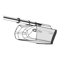
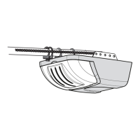
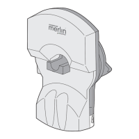
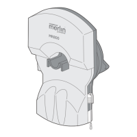
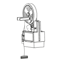
ATTACH MANUAL RELEASE ROPE & HANDLE –
Thread one end of rope (1) through hole in top of red handle so "NOTICE" reads right side up as shown (3). Secure with an overhand knot (2).
Knot should be at least 25mm (1") from end of the rope to prevent slipping. Thread other end of rope through hole in release arm of the outer trol-
ley (4). Adjust rope length so that handle is 1,8m (6 feet) above the floor. Secure with an overhand knot.
Note: If it is necessary to cut rope, heat seal cut end with a match or lighter to prevent fraying.
CONNECT ELECTRIC POWER
TO AVOID INSTALLATION DIFFICULTIES, DO NOT RUN
THE GARAGE DOOR OPENER UNTIL INSTRUCTED TO DO SO.
Connect the opener to a mains which is properly
EARTHED according to the wiring instruction tag attached to
power supply cord (and as specified by local code).
Connect the door opener only to an outlet controlled
by a double pole switch.
13
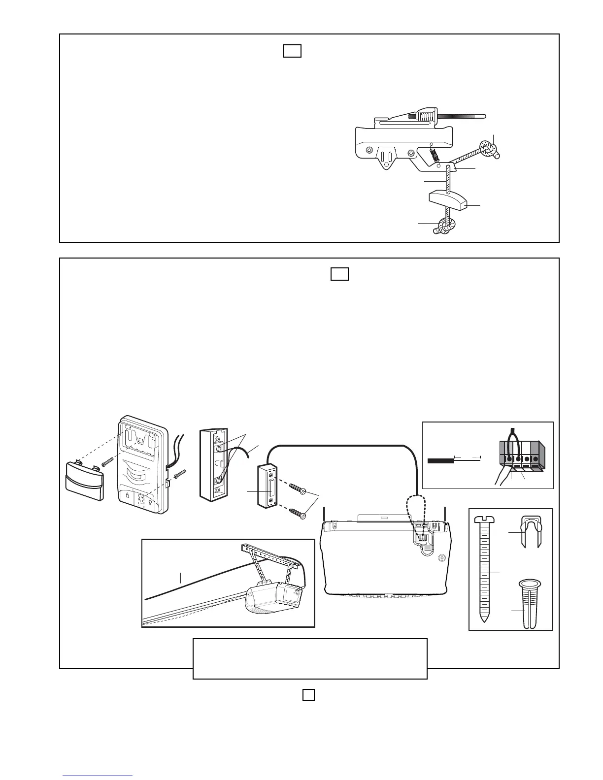
INSTALL WIRED DOOR CONTROLS (optional accessory) –
Locate wired door controls where the garage door is visible, away from door and door hardware, out of the reach of children and in a height
of at least 1.5m.
Serious personal injury from a moving garage door may result from misuse of opener. Do not allow children to operate the wired door con-
trols or remote control transmitters.
Fasten the caution label on the wall near wired door controls as a reminder of safe operating procedures.
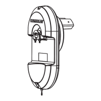
There are 2 screw terminals (1) on the back of the wired door controls (2). Strip about 6mm (1/4") of insulation from bell wire (4). Separate wires
enough to connect the white/red wire to terminal screw 1 and the white wire to terminal screw 2.
Fasten wired door controls to an inside garage wall with sheet metal screws (3) provided. Drill 4mm (5/32") holes and use anchors (6) if installing into
drywall. A convenient place is beside the service door and out of reach of children.
Run the bell wire up the wall and across the ceiling to the garage door opener. Use insulated staples (5) to secure wire. The receiver terminal screws
(7) are located on the back panel of the opener. Connect the bell wire to the terminal screws as follows: white/red to 1 and white to 2.
14
4
2
3
1
WHT
-2
RED
-1
4
5
3
6
6mm
7
8
LOCK
LIGHT
Push Bar Cover
OPERATION OF THE WIRED DOOR CONTROLS
Press to open or close the door. Press again to reverse the door
during the closing cycle or to stop the door during opening cycle.
9
 Loading...