12
2
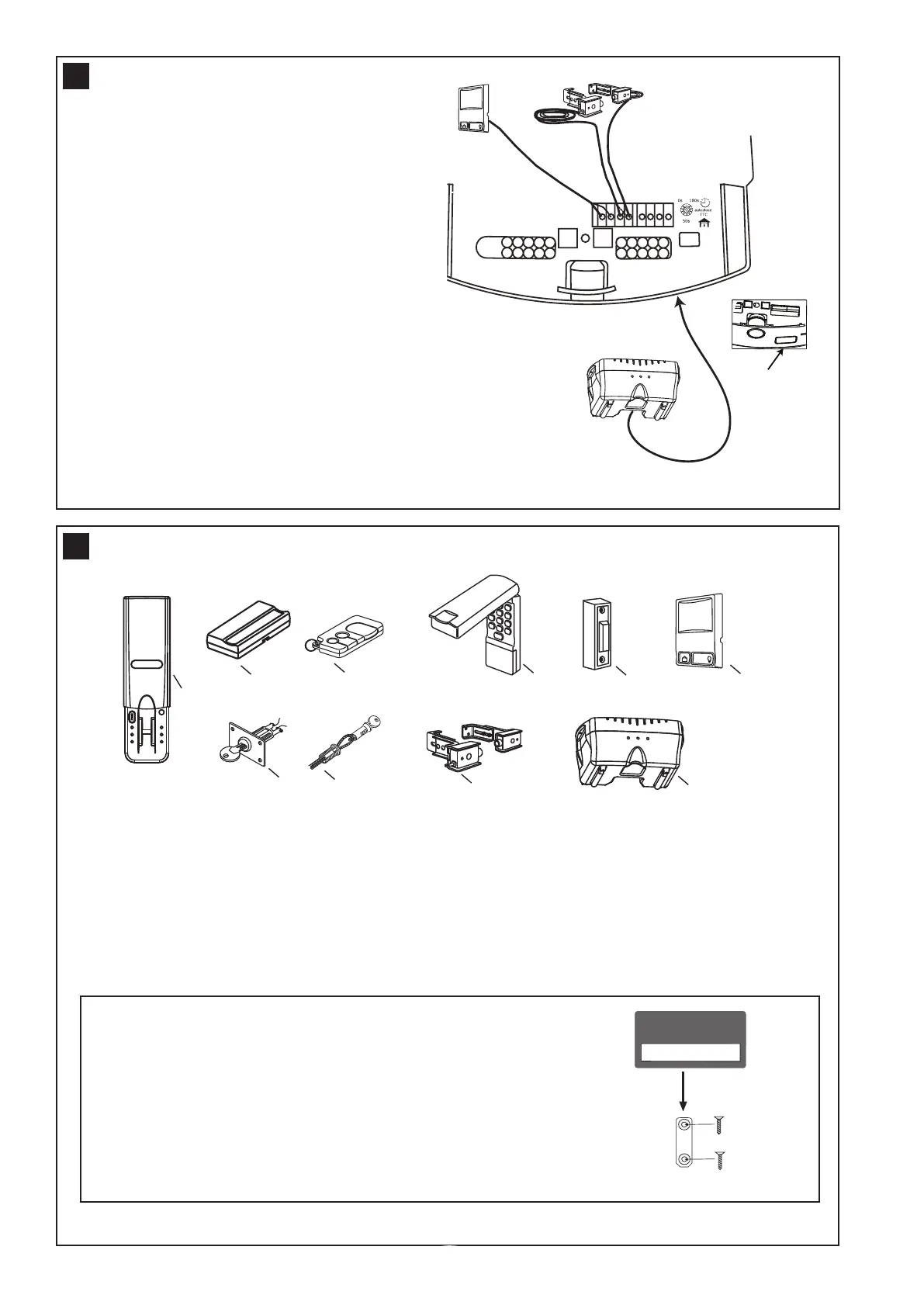
3
LOCK
LIGHT
Remove tab
at base of opener
before connecting
Standby power unit
fig 1
1.Multifunction control panel
Connect white/red wire to the red “wired wall
control” quick connect terminal and the white wire
to the white “wired wall control” quick connect
terminal.
2.The Protector System™ (IR Beams)
Connect both white wires to the white “safety beam”
quick connect terminal and both white/black wires to
the grey “safety beam” quick connect terminal.
3. Standby power unit
Connects via plug (fig 1) and lead provided with the
unit into the base of the opener.
Note: Timed auto-close function is enabled by
turning the dial to the required time. The Protector
System
TM
(IR Beams) must be installed before
using this function. Timer trim pot must be set to
zero when the Protector System
TM
(IR Beams) is
installed.
20
1. Model C379 Fingerprint keyless entrypad
2. Model 84330AML 1 channel transmitter
3. Model 84335AML 3 channel mini transmitter
4. Model 8747AML Keyless entry system
5. Model 75AML Illuminated button
6. Model 845AML Multi-function control panel
7. Model 760AML Outdoor keyswitch
8. Model 1702AML Keyed outdoor emergency release
9. Model 770AML The Protector System
TM
(IR Beams)
10. Model C475 Standby power unit
ACCESSORIES
21
ENROLL
FAIL
RETRY
SEND
PASS
READY
ENROLL
LOCK
LIGHT
1
23 4
5
6
7
8
9
10
SPECIAL FEATURES
Transmitter wall mount bracket
• Attach bracket to wall using the two flat head screws
provided.
• Slide the transmitter onto bracket.
• Fix the warning against entrapment label near the wall control
(refer section 15).
NOTE: Do not over tighten screws, allow enough clearance to
slide transmitter down onto the bracket.