To protect small children, install the Protector System™ no
higher than 4"-6" (100mm-150mm) above the garage floor.
Disconnect power to the garage door opener before installing
the Protector System™.
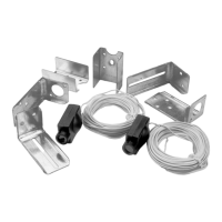
Figure 1: Facing the door from inside the garage
The Protector System
™
- Safety Reversing Sensor Model 770EML
Installation procedures are the same for sectional and one-piece doors.
Look at the label on the connector end of each case to identify the
sensors.
The sending eye transmits an invisible light beam to the receiving eye.
If an obstruction breaks the light beam while the garage door is
closing, the door will stop and reverse to full open position.
The units can be installed on either side of the garage door (Figure 1)
as long as the sun never shines directly into the receiving eye lens,
but the brackets must be connected and fastened so that the sending
and receiving eyes face each other as shown in Figure 1.
The brackets must be securely fastened to a solid surface such as the
studs on either side of the door, or add a piece of wood at each
location if installing in masonry construction.
The invisible light beam path must be unobstructed. No part of the
garage door (or door tracks, springs, hinges, rollers or other
hardware) can interrupt the beam while the door is closing. If it does,
use a piece of wood to build out each sensor mounting location to
the minimum depth required for light beam clearance.
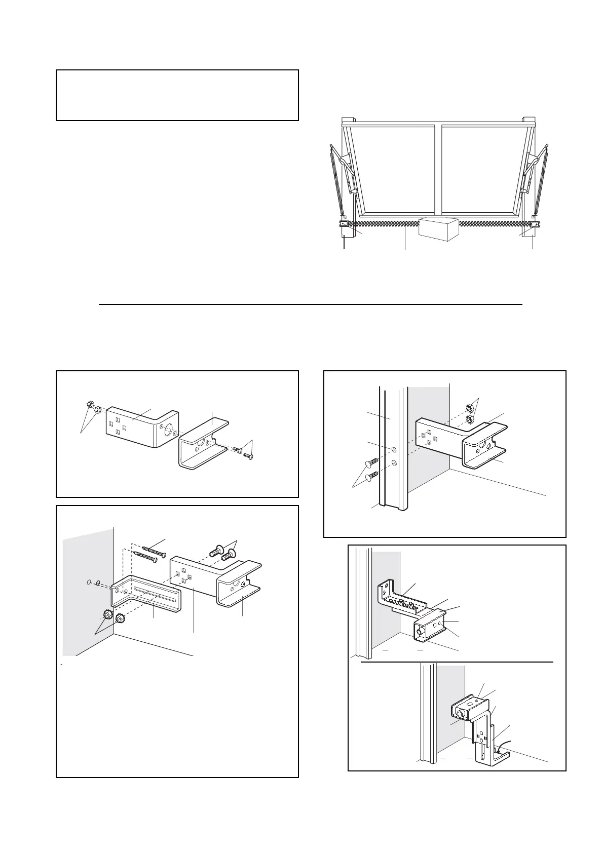
ASSEMBLY PROCEDURES
Figure 2
• Discard slotted bracket. Drill 3/8" (9,5mm) holes in each
track and fasten securely with hardware as shown.
Figures 2, 3 and 4 show recommended assembly of bracket(s) and "C" wrap based on the wall installation of the sensors on each side of
the garage door shown above, or on the garage door tracks themselves.
Figure 5 shows variations which may fit your installation requirements better. Make sure the wraps and brackets are aligned so the
sensors will face each other across the garage door.
• Connect each assembly to a slotted bracket, using the
hardware shown. Note alignment of brackets for left and
right sides of the door. Finger tighten the lock nuts.
• Use bracket mounting holes as a template to locate and drill
(2) 3/16" (4,8mm) diameter pilot holes on both sides of the
garage door, 4"-6" (100mm-150mm) above the floor (but not
exceeding 6" (150mm).
• Attach bracket assemblies with 1/4"x1-1/2" lag screws as
shown.
• Adjust right and left side bracket assemblies to the same
distance out from mounting surface. Make sure all door
hardware obstructions are cleared. Tighten the nuts securely.
Figure 5
Figure 4
2-EN
 Loading...