DIAGNOSTICS
DIAGNOSTICS
DIAGNOSTICS
1
2
3
4
5
10W 12V
CONTROL BOARD
Plug-In Transformer
(back of outlet housing)
Outlet
Outlet
J15 Plug
Outlet Housing
Photoelectric Sensor
Reflector
Black
Black
Red
Red
Black
White
Green
Incoming Power
HOT
NEUTRAL
GROUND
Battery
12V 7AH
WIRING AND ADJUSTMENTS
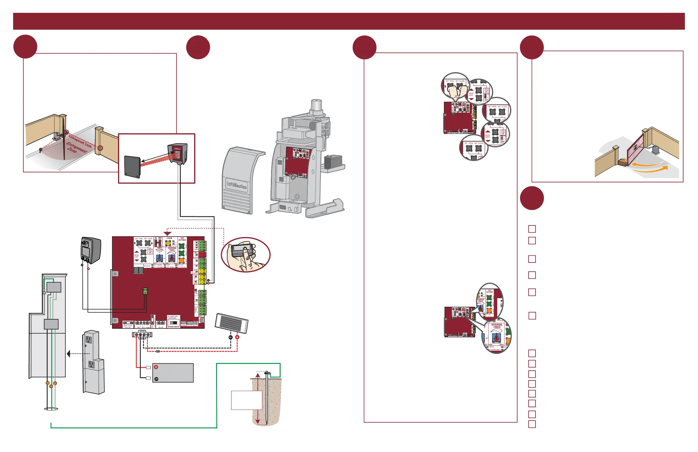
FINE TUNE THE FORCE
The REVERSAL FORCE DIAL on the control board is used for fine
tuning the force in cases where wind or environmental changes
may affect the gate travel. Based on the length and weight of the
gate it may be necessary to make additional force adjustments.
The force setting should be high enough that the gate will not
reverse by itself nor cause nuisance interruptions, but low enough
to prevent serious injury to a person. The force setting is the same
for both the open and close gate
directions.
1. Open and close the gate with
the test buttons.
2. If the gate stops or reverses
before reaching the fully open
or closed position, increase
the force by turning the force
control slightly clockwise.
3. Perform the “Obstruction
Test” after every force setting
adjustment.
1. Open and close the gate with the test buttons, ensuring that the
gate is stopping at the proper open and close limit positions.
2. Place a solid object between the open gate and a rigid structure.
Ensure that the gate, the solid object, and the rigid structure can
withstand the forces generated during this obstruction test.
3. Run the gate in the close direction. The gate should stop and
reverse upon contact with the solid object. If the gate does not
reverse off the solid object, reduce the force setting by turning
the force control slightly counter-clockwise. The gate should
have enough force to reach both the open and close limits, but
MUST reverse after
contact with a solid
object.
4. Repeat the test for
the open direction.
Turn off the AC power from the main power source circuit
breaker. Connect the earth ground rod, incoming power,
battery, and plug-in transformer (see images below). Refer to
your manual for complete wiring information.
EARTH GROUND ROD
Install the earth ground rod
within 3 feet (.9 m) of the
operator.
Check national
and local codes
for proper depth
PROGRAM REMOTE CONTROL
1. Press and release the LEARN
button on the control board
(operator will beep and green
XMITTER LED will light).
2. Press the remote control button.
The operator will time out of
programming mode after 30 seconds.
Install Monitored Entrapment Protection Device
Connect Power Wiring and Earth Ground Rod Set the Limits and Force
Perform the Obstruction Test
Installation Checklist
Are all the wiring and connections tightly connected?
Is the AC power on? If the operator is left running on battery only, it
will drain the battery and will result in a service call.
Check the battery and battery connections. Make sure there is one 12V
battery. Replace battery if depleted to less than 11.5 V.
Make sure the antenna is in place when using wireless dual gates or
on-board transmitters. Operator will be intermittent at times without it.
Remove the protective anti-scratch film from the photoelectric sensors.
Leaving the film on can result in poor sensitivity as the film
decays/yellows/peels.
Confirm whether the site should be fail safe or secure and set the
operator accordingly.
Confirm operation of the following (if applicable):
Entrapment protection devices
Loops
TES relay
SOS/emergency transponders
Check operation of ALL legacy receivers using the MAX transmitter
Timer-to-Close setting
Quick close setting
Anti-tailgate setting
Check the following before leaving the site:
INITIAL LIMITS AND FORCE ADJUSTMENT
1. Press and release the SET
OPEN and SET CLOSE
buttons simultaneously to
enter limit setting mode.
2. Press and hold one of the
MOVE GATE buttons to move
the gate to the open or close
limit.
3. Press and release the SET
CLOSE or SET OPEN button
depending on which limit is
being set.
4. Press and hold one of the
MOVE GATE button to move
the gate to the other limit.
5. Press and release the SET CLOSE or SET OPEN button depending
on which limit is being set.
6. Cycle the gate open and close. This automatically sets the force.
When limits are set properly the operator will automatically exit limit
setting mode.
This operator contains an inherent (internal) entrapment protection
system and REQUIRES the addition of a LiftMaster external
monitored entrapment protection system (non-contact photoelectric
sensor or contact edge sensor) for EACH entrapment zone prior to
gate movement. System includes three monitored entrapment
protection inputs to cover all entrapment zones (and a total of six
inputs with the optional expansion board). Refer to the manual for
complete information.
SOLAR PANEL (OPTIONAL)
10W minimum - 30W maximum, wired in parallel
(requires K94-37236 battery harness)
 Loading...