EasyManua.ls Logo

Champlain ACM-123-2 User Manual

Default Icon
8 pages
To Next Page IconTo Next Page
Page #1 background imageLoading...
Page #1 background image
ACM-123-2
Hardware • Jeu de pièces
Champlain Plastics Inc.
87 Pillsbury Road
Rouses Point, NY 12979
(INS-123-2-rev2)
P1
x1
P6
x2
P7
x2
P8
x1
P9
x2
P2
x2
P3
x2
P4
x2
P5
x2
By/Par : Champlain Plastics Inc.
87 Pillsbury Road, Rouses Point, NY 12979 INS-123-2-rev2
ACM-123-2
x20
!
x8
"
x24
#
x 1
$
x 2
%
IMPORTANT SAFETY INSTRUCTIONS
CAUTION: To prevent damage to the steps and to
minimize risk of injury follow these instructions carefully.
• Install steps on a solid base.
• These steps must be used only to enter and exit the pool.
Any other use could damage the steps and pool structure.
• NO JUMPING.
• NO DIVING.
• To prevent entrapment or drowning, do not
swim through, behind or around the steps.
NOTE: Steps are designed and manufactured
for above ground pools which are 48", 52"
or 54" in height.
Steps must be removed from the pool
and stored in a dry place for the winter.
NOTES IMPORTANTES DE SÉCURITÉ
ATTENTION : Afin d'éviter d'endommager l'échelle et pour
minimiser les risques de blessures, respecter attentivement
les indications suivantes.
• Installer les escaliers sur une base solide.
• Les escaliers doit être utilisée seulement pour entrer et
sortir de la piscine. Toute autre utilisation pourrait
endommager les escaliers et la structure de la piscine.
• NE PAS SAUTER.
• NE PAS PLONGER.
• Ne pas nager à travers, derrière ou autour les escaliers
afin d'éviter d'y demeurer coince et de se noyer.
NOTE : Les escaliers est conçue et fabrique pour convenir
aux piscines hors terre d'une hauteur de 48", 52" ou 54".
Les escaliers doit être sorti de la piscine et remisé
dans un endroit sec pour l'hiver.
Note: Approx. 50 lbs (22,7kg) pea gravel
needed to complete installation
Note: Environ 50 lbs (22.7kg) de petit gravillon
seront nécessaires afin de compléter l'installation
x 2
&
STEP 6
Two people are needed to
put the steps in the pool.
WARNING: The space
between the pool inner wall
and the step should be 2”
in order to prevent
entrapment and liner
damage.
Attach arms (P6) to pool deck
using 12 screws (1). Align
and attach arms (P6)
to posts (P4 & P5) using 4
screws (1). Do not use an
electric drill over water.
Note:
Wood spacer(s)
may be used
if deck is lower
than pool deck.
ÉTAPE 6
2 personnes sont
nécessaires pour mettre
l'escalier dans la piscine.
AVERTISSEMENT :
L’espace entre la paroi
intérieure de la piscine et
l’escalier doit être de 2” afin
d’éviter qu’une personne
n’y demeure coincé et
d’endommage la toile
de piscine.
Attacher les bras (P6) au deck
de piscine en utilisant 12 vis
(1). Aligner et attacher les bras
(P6) aux poteaux (P4 & P5) en
utilisant 4 vis (1). Ne pas
utiliser de tournevis
électrique au-dessus de
l'eau.
Note : Des espaceurs
de bois peuvent être
utilisés si le deck est plus
bas que la piscine.
!
!
E7
#12 x 1” #12 x 3/4” #8 x 1”
P6
Assembled/Assemblé
Pool
Piscine
Deck
Wood Spacer(s)
Espaceurs de bois
!
P6
2”
IMPORTANT
P4
Question and Answer IconNeed help?

Do you have a question about the Champlain ACM-123-2 and is the answer not in the manual?

Champlain ACM-123-2 Specifications

General IconGeneral
BrandChamplain
ModelACM-123-2
CategoryLighting Equipment
LanguageEnglish

Summary

ACM-123-2 Product Overview and Safety

Parts Identification

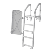
Identifies all parts (P1-P9) and hardware (1-6) included for assembly.

Important Safety Instructions

Provides essential safety precautions for pool step usage and installation to prevent accidents.

Installation and Storage Notes

Details pool height compatibility (48", 52", 54") and winter storage requirements.

ACM-123-2 Assembly Instructions

Step 1: Attach Post Holders

Guides attaching post holders (P2) to the underside of steps (P1) using screws.

Step 2: Assemble Posts and Rails

Details inserting posts (P4, P3) and attaching handrails (P5) to the steps.

Step 3: Secure Posts to Steps

Secures the posts (P4) to the underside of the steps (P1) using screws as illustrated.

Step 4: Refer to ACM-123A Guide

Directs users to consult the ACM-123A instruction guide for further steps.

Step 5: Install Caps

Instructs on snapping the center cap (5) and bottom caps (6) into their respective positions.

Step 6: Attach Arms to Deck and Posts

Connects arm supports (P6) to the pool deck and step posts (P4, P5).

Safety Warning: Pool Wall Clearance

Highlights the critical 2" space requirement between the pool wall and steps.

Note on Wood Spacers

Explains the use of wood spacers for decks lower than the pool deck.

ACM-123A Ballast and Adjustable Feet Assembly

Assemble Adjustable Feet

Details the assembly of adjustable feet (P11) using legs, feet, screws, and caps.

Attach Ballast

Guides attaching the ballast (P10) to the steps using clamps and screws, noting filling hole orientation.

Anti-Slip Mat Installation (ACM-123-8)

Step 1: Align Pins with Large Holes

Instructs to insert anti-slip mat pins into the large holes of the steps.

Step 2: Secure Pins with Locking Device

Guides pulling pins through with pliers to engage the locking device.

ACM-123P Barrier Installation

Step 1: Attach Anchors to Step

Details attaching anchors (1) to the underside of the step using screws and washers.

Step 2: Install Barrier

Guides sliding the barrier (7) into anchors (1) and securing it with bolts.

Related product manuals