INSTALLATION INSTRUCTIONS
Get the Clearest Picture and Sound
™
Channel Master by PCT
2151 East Broadway Road, Ste 211 | Tempe, AZ 85282-1933 | USA
Tel +1.480.813.0925 | Fax +1.480.545.1080
© 2008 Channel Master by PCT a division of PCT International, Inc
RCCPP and Channel Master are trademarks of PCT International, Inc.
Channel Master trademark is used under license. Specications subject to change.
All rights reserved. Pub PCTCM.3410341234143418.INST.20080721
www.channelmasterintl.com
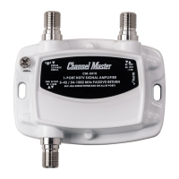
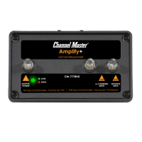
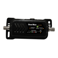
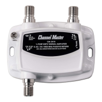
1. Install type F-male connectorized input coaxial cable from the cable
operator or from the antenna to the “RF IN” port on the amplier.
2. Install type F-male connectorized RF coaxial cable from the “RF OUT”
port(s) to the television set, set top box, or cable modem.
3. Verify AC voltage rating of power source conforms with AC/DC adapter.
4. Connect F-male connectorized RF coaxial cable between “PWR IN” port on
the drop amplier and power adapter F-type connection.
5. Connect the power adapter to AC voltage source, Installation is complete
MULTIMEDIA DROP AMPLIFIERS
CM-3410 (PCT-MA2-M)
CM-3412 (PCT-MA2-2P)
CM-3414 (PCT-MA2-4P)
CM-3418 (PCT-MA2-8P)
INSTALLATION INSTRUCTIONS
Get the Clearest Picture and Sound
™
Channel Master by PCT
2151 East Broadway Road, Ste 211 | Tempe, AZ 85282-1933 | USA
Tel +1.480.813.0925 | Fax +1.480.545.1080
© 2008 Channel Master by PCT a division of PCT International, Inc
RCCPP and Channel Master are trademarks of PCT International, Inc.
Channel Master trademark is used under license. Specications subject to change.
All rights reserved. Pub PCTCM.3410341234143418.INST.20080721
www.channelmasterintl.com
1. Install type F-male connectorized input coaxial cable from the cable
operator or from the antenna to the “RF IN” port on the amplier.
2. Install type F-male connectorized RF coaxial cable from the “RF OUT”
port(s) to the television set, set top box, or cable modem.
3. Verify AC voltage rating of power source conforms with AC/DC adapter.
4. Connect F-male connectorized RF coaxial cable between “PWR IN” port on
the drop amplier and power adapter F-type connection.
5. Connect the power adapter to AC voltage source, Installation is complete
MULTIMEDIA DROP AMPLIFIERS
CM-3410 (PCT-MA2-M)
CM-3412 (PCT-MA2-2P)
CM-3414 (PCT-MA2-4P)
CM-3418 (PCT-MA2-8P)