14Réf. : CH - 1254 - I - 0 - EN
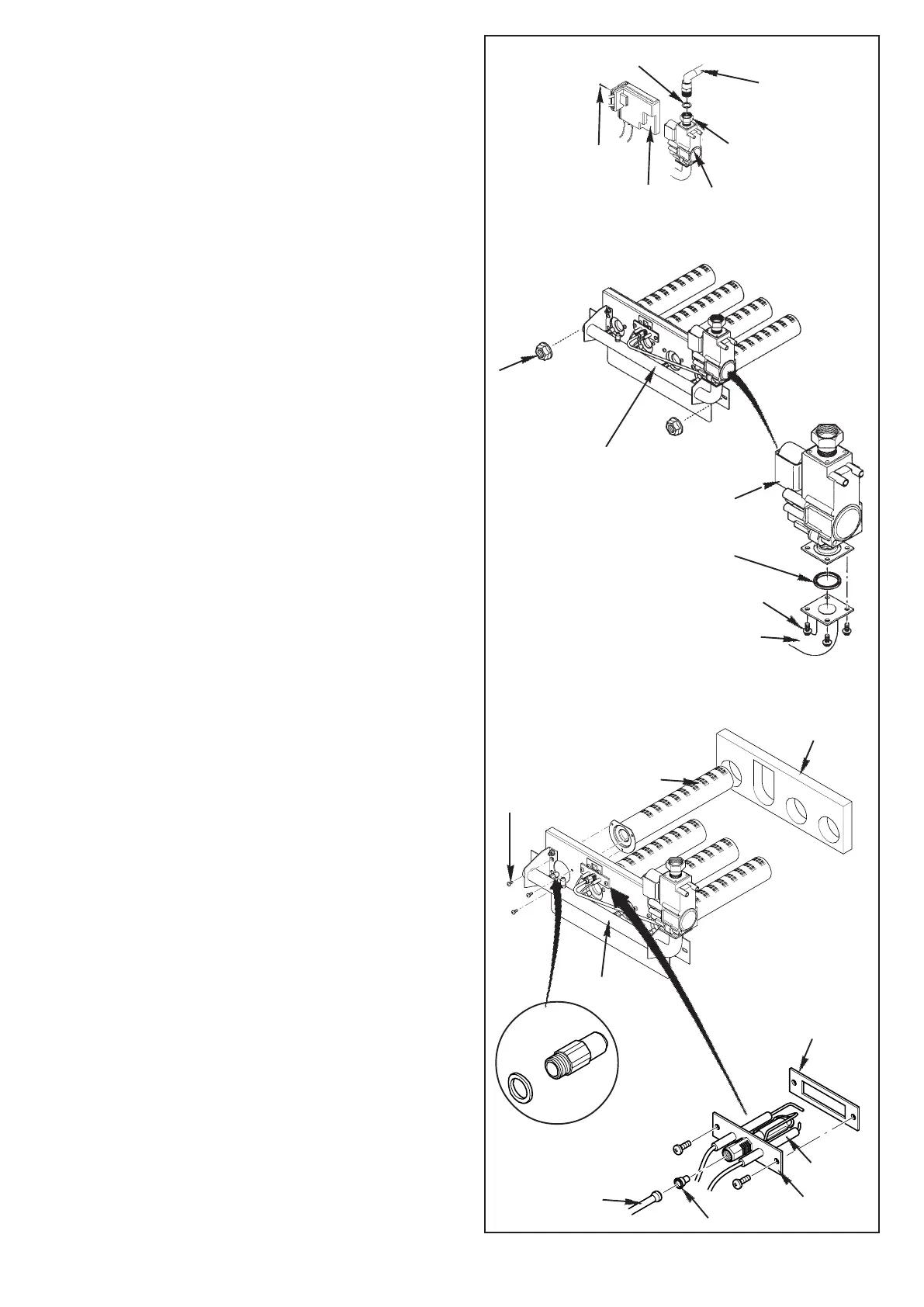
10.3 Gas Valve
1. Undo the disconnecting union on the gas inlet. Remove
the screw securing the burner ignition control to the
gas valve. Draw the control off the valve.
2. Undo the two nuts securing the valve, injector mani-
fold and burner assembly to the boiler.
3. Hold the manifold and carefully draw the assembly
away from the boiler. Retain the washer from the gas
inlet connection.
4. Undo the pilot feed pipe from the gas valve, and
slacken it at the pilot burner to allow it to swing clear.
5. Undo the four screws securing the gas valve to the
injector manifold. Remove the valve and seal.
6. Check the condition of the seal previously removed
before fitting the new valve to the injector manifold.
Replace as necessary.
7. Reassemble in reverse order and check the condi-
tion of the seal to be used on the disconnecting union.
Replace as necessary.
10.4 Burner (s)
1. Undo the disconnecting union on the gas inlet.
Remove the screw securing the burner ignition control
to the gas valve. Draw the control off the valve.
2. Undo the two nuts securing the valve, injector mani-
fold and burner assembly to the boiler.
3. Hold the mani fold and carefully draw the assembly
away from the boiler. Retain the washer from the gas
inlet connection.
4. Carefully draw the insulation piece away over the
burners .
5. Undo the screws securing the burner(s) to be replaced.
Remove the burner(s).
6. Reassemble in reverse order, replacing the insulation
piece if it is damaged.
10.5 Injector(s)
1. Using a suitable spanner undo from the manifold the
injector(s) to be replaced.
2. Reassemble in reverse order using a new sealing
washer for each injector.
10.6 Pilot Assembly
1. Disconnect and remove the pilot feed pipe. Pull the
electrode leads off the gas valve burner ignition
control and unclip them from the separation brackets.
2. Undo the pilot bracket securing screws. Withdraw the
bracket from the burner mounting plate. Carefully
remove the pilot injector from the bracket.
3. Inspect the injector and replace if it is blocked or
damaged. Check the condition of the pilot bracket
sealing gasket and replace if necessary.
4. The new pilot assembly must be fitted as shown, with
the spark electrode to the right.
5. Clip the electrode leads into the separation brackets.
Ensure that the leads do not cross over each other.
6. Reassemble in reverse order.
Gas Cock
Sealing Washer
Disconnecting
Union
Gas Valve
Securing
Screw
Burner
Ignition
Control
Securiting
Nuts (x2)
Manifold
N04334.TIF
N04338.TIF
Gas Valve
Quad Seal
Valve Securing
Screws
Burner Manifold
Securiting
Nuts (x3)
Manifold
Insulation
Burner
Injector and Washer
Sealing Gasket
Spark
Electrode
Insulation
Pilot Bracket
Pilot Feed Pipe
N04340.TIF
N04337.TIFN04342.TIF