25
FR
ENG
must be carried out using soapy water
or special products. Do not use naked
flames. The conversion to different
gas must be carried out exclusively by
authorized technical personnel.
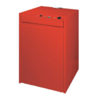
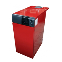
4.5 REMOVING THE CASING
It is possible to completely disassemble
the shell for an easy maintenance of
the boiler following these simple
instructions:
– Remove the boiler top which is fixed
with pressure plugs.
– Remove the panelboard.
– To remove the door, unscrew com-
pletely the screw fixing the top hinge
and lift the door, removing it from
the fixed plug of the bottom hinge.
– Remove front and back panels by loo-
sening the four nuts which fix them
to the panels side.
– Remove the sides.
4.6 MAINTENANCE
In order to ensure functionality and
efficiency, the device must undergo
annual checks carried out by quali-
fied technical personnel.
4.6.1 Checking and cleaning
the iron cast heat exchanger
Follow the operations below to clean
the iron cast heat exchanger:
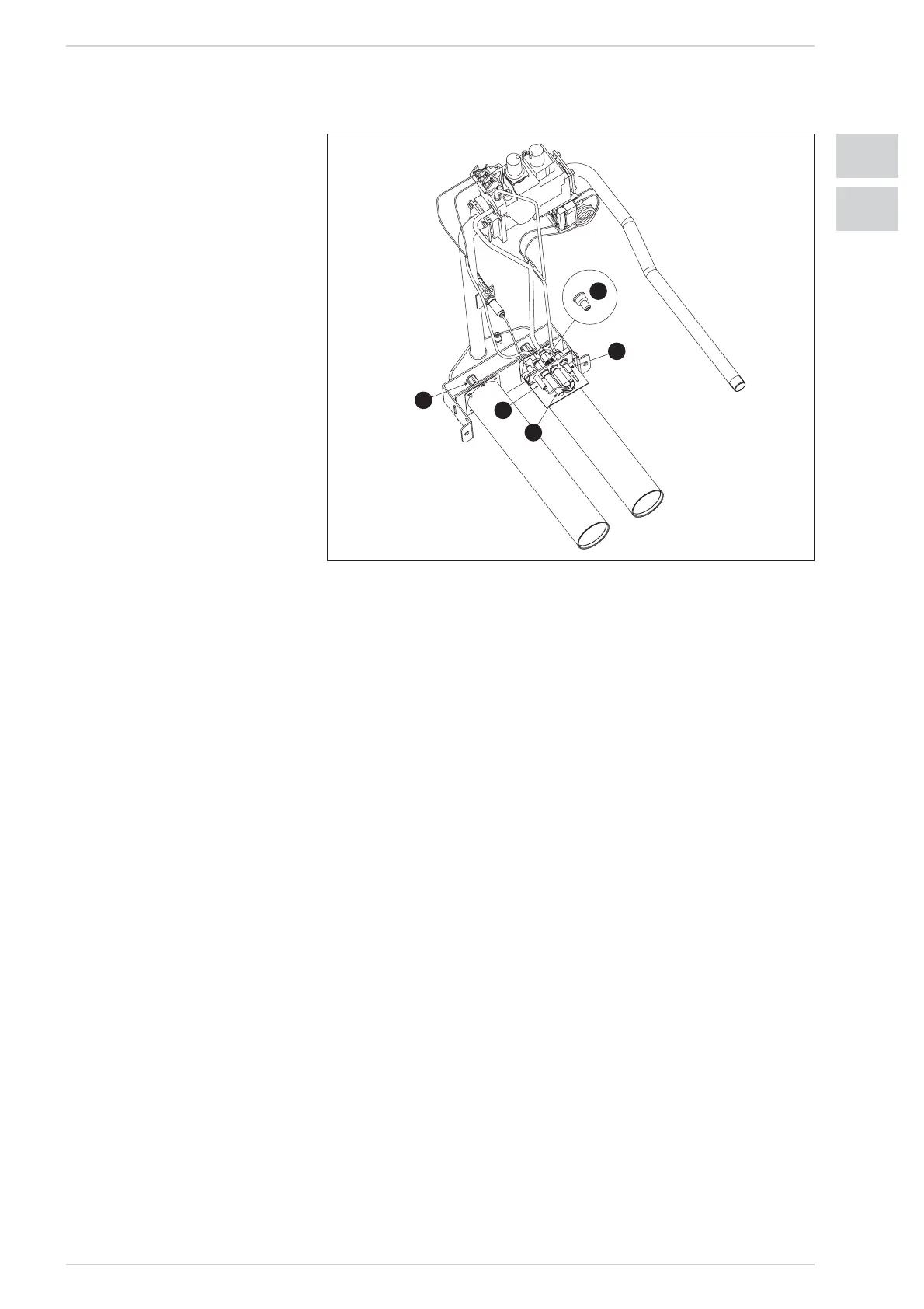
– Take off the boiler top.
–
Remove the smoke chamber cleaning
plate by unscrewing the fastening
screws in the EDENA EVOLUTION EF
1.22-1.31 boilers.
–
Remove the smoke chamber comple-
tely unscrewing the two nuts from
the back side and the nut from the
front side of EDENA EVOLUTION EF
1.39÷1.61 boilers.
– Extract the burner assembly by
unscrewing the four screws which
fix it to the valve flange.
– With the appropriate brush, reach
down to the rows of plugs of the cast
iron exchanger from the top and
scrape off any scale with vertical
movements.
– Remove the burners from the nozzle
holder header and throw a jet of air
inside them so that any dust can be
removed. Make sure that the top
drilled part of the burners has no
scale left.
–
When disassembling and reassem-
bling the burners be careful not to
force any delicate parts, such as the
thermocouple drill or the ignition unit.
– Scrape off any scale from the boiler
bottom and reassemble all the parts
checking the position of the gaskets.
– Check the stack making sure the flue
is clean.
– Check the correct operation of the
equipment.
4.6.2 Checking and cleaning
the main burner
Address a water jet inwards the bur-
ners so to remove the accumulated
dust. Ensure that the burner perfora-
ted upper part is free from scale.
When disassembling and reassem-
bling the burner, do not force on the
delicate components, such as the
thermocouple, thermopile and pilot
burner.
4.6.3 Checking and cleaning
the pilot burner
Clean the primary air inlet hole and
pilot nozzle with an air jet. Check that
the burner flame licks the thermocou-
ple and thermopile tip completely.
4.6.4 Checking the thermopile
efficiency
If correctly heated, the thermopile
generates the current required for
the gas valve to work. If correctly hea-
ted, the thermopile generates
700/800 mV voltage, which must be
measured using a millivoltmeter on
the two cable connection terminals to
the gas valve.
The operator of the gas valve requi-
res about 300mV voltage.
The poor voltage of the thermopile
prevents the system from working.
4.6.5 Checking the
thermocouple efficiency
If heated correctly, the thermocouple
generates the voltage required for
keeping energised the magnet that
controls the gas passage opening to
the pilot burner. Normally, the ther-
mocouple generates 5/7 mV, which
must be measured using a millivolt-
meter on the two thermocouple con-
nection terminals to the manual reset
safety thermostat. The poor voltage
of the thermocouple prevents the
system from working.
4.6.6 Checking the gas valve
efficiency
Preventive maintenance operations
cannot be performed on the gas
valve. Only the magnetic unit can be
replaced.
Anyway, verify cleanness and remove