8
Introduction/Operation Product Manual - Perma-Cyl
®
w/ FlexFill™ Piping Option
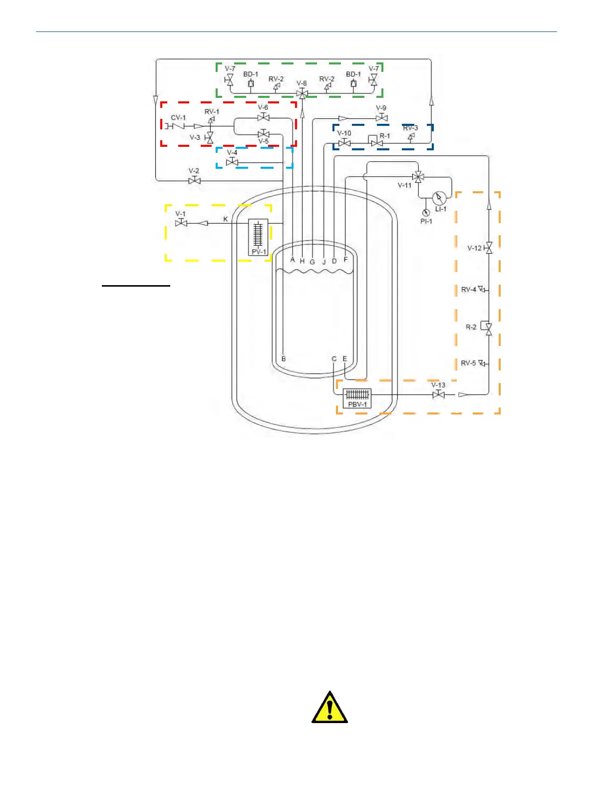
Figure 1 - Schematic for 1000HP/VHP, 1500HP/VHP, 2000HP and 3000HP models.
valves. Product owing into the bottom of the tank will raise
the pressure and product owing into the top of the tank will
lower the pressure. Adjusting each valve properly will allow
the driver to hold a consistent pressure in the tank throughout
the entire delivery.
During a rst ll, only ll the vessel to 75% full to allow
liquid expansion experienced with a new "hot" tank. Each
ll there after can be lled to 100% full. Please refer to
the Installation section of this manual for detailed lling
procedures.
Caution! If liquid can be trapped in the
transfer system, a suitable relief
valve must be installed to prevent
over pressurization.
Color Code:
Fill Circuit
PB Circuit
Economizer Circuit
Gas Use Circuit
Safety Circuit
Liquid Circuit
Primary Plumbing Circuits
(Refer to Figure 1)
Fill
The Perma-Cyl w/ FlexFill has a top and bottom ll circuit
that replaces the top oat assembly so the driver can control
the tank pressure while lling the Perma-Cyl MicroBulk
Storage Tank. The ll circuit consists of a top ll valve (V-6),
a bottom ll valve (V-5), a ll check valve (CV-1), and a
hose drain valve (V-3). The ll line check valve has a service
tting on the inlet side that provides the sole connection for
the liquid delivery vehicle.
The hose drain valve (V-3) can be used to both purge the ll
hose before lling the tank or to depressurize the ll hose
after lling the tank.
The driver controls the pressure in the vessel during the ll
process by adjusting the ow through the top and bottom ll